Download
1 / 40
480 likes | 758 Views
Rayat Shikshan Sanstha’s S.M. Joshi College Hadapsar-028 Department of Electronics Science. Operational amplifier. Presented by- Dr. Kakade P.K.

E N D
RayatShikshanSanstha’s S.M. Joshi College Hadapsar-028 Department of Electronics Science Operational amplifier Presented by- Dr. Kakade P.K
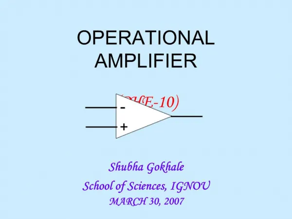
The operational amplifier or op-amp is a circuit of components integrated into one chip. A typical op-amp is powered by two dc voltages and has an inverting(-) and a non-inverting input (+) and an output.An op amp is an electronic device which provides a voltage output based on the voltage input introduction
Basic op-amp introduction
Operational Amplifiers Five important pins • 2 – The inverting input • 3 – The non-inverting input • 6 – The output • 4 – The negative power supply V- (-Vcc) • 7 – The positive power supply V+ (+Vcc) introduction
Operational Amplifiers • The output of the op amp is given by the following equation: Vd = E1 – E2 and Vo = AVOL(Vd) • AVOL is called the open-loop voltage gain because it is the gain of the op amp without any external feedback from output to input introduction
Operational Amplifiers • Positive Saturation – where the output voltage exceeds the positive power input introduction
Operational Amplifiers • Linear Region – where the output voltage is linear based on A (gain) introduction
Operational Amplifiers • Negative Saturation – where the output voltage would be less than the negative power input introduction
Operational Amplifiers introduction
What do they really look like? introduction
IC Circuit introduction
Operational Amplifiers introduction
Operational Amplifiers • An ideal op-amp has infinite gain and bandwidth, we know this is impossible. • However, op-amps do have: • very high gain • very high input impedance(Zin = ∞) • very low output impedance (Zout = 0) • wide bandwidth. introduction
Application in op-amp • There are 2 types of application in op-amp • Linear application • Non-linear application • Linear application is where the op-amp operate in linear region: • Assumptions in linear application: • Input current, Ii = 0 • Input voltage: V+=V- • Feedback at the inverting input application
Application in op-amp • Non-linear application is where the op-amp operate in non-linear region • By comparing these two input voltages: positive input voltages, V+ and negative input voltage, V- where: VO = VCC if V+ > V- VO = -VEE if V+ < V- • Input current, Ii = 0 application
Applications of op-amp • Comparator • Inverter • Audio amplifier • Difference Amplifier • Filter • Summing Amplifier application
Op-amp Circuit Application • Inverting Amplifier • Non-Inverting Amplifier • Summing Amplifier • Unity Follower • Difference Amplifier • Integrators • Differentiators application
Application: Inverting amplifier • Provide a constant gain multiplier • Input signal is connected to the inverting input of the op-amp. Therefore, the output signal is 180 degree out of phase from the input signal • Rf is the feed-back resistor to control the voltage gain of the op-amp application:inverting amplifier
Summary of op-amp behavior Vo = A(V+ - V) Vo/A = V+ - V Let A infinity then, V+ - V 0 application:inverting amplifier
Summary of op-amp behavior V+ = V I+ = I = 0 Seems strange, but the input terminals to an op-amp act as a short and open at the same time application:inverting amplifier
To analyze an op-amp circuit for linear operation • Write node equations at + and - terminals • (Ii=I+ = I-= 0) • Set V+ = V- • Solve for Vo application:inverting amplifier
Analysis of inverting amplifier If Ii I1 application:inverting amplifier
Application:Non-inverting amplifier application:non-inverting amplifier
I2 I1 Vi Ii Non-inverting configuration
Application: Summing amplifier introduction
Rf R1 V1 V2 V3 R2 R3 Summing Amplifier This circuit is called a weighted summer
Application: Unity Follower application:unity-follower
Application:Difference amplifier introduction
Application:Instrumentation Amplifier Buffer (Penimbal) Difference amplifier introduction
Application:Integrator I IC introduction
Application:Differentiation application:differentiator
Exercise 1 Find VO? exercise
Exercise 2 Find V2 and V3? exercise
Exercise 3 Find VO? exercise
Exercise 4 Find VO? exercise
Recall: Non-linear application in op-amp • Non-linear application is where the op-amp operate in non-linear region • By comparing these two input voltages: positive input voltages, V+ and negative input voltage, V- where: VO = VCC if V+ > V- VO = -VCC if V+ < V- • Input current, Ii = 0 non-linear application
Non-linear application:Comparator (Pembanding) non-linear application:comparator
VS(V) t Vo(V) 10 t -5 Non-linear application:Comparator (Pembanding) (a) Input Voltage of Comparator Compare V+ and V- V+=0 V-=VS When: VS>0,V+>V- so Vo=10V VS<0,V+<V- so Vo=-5V (b) Output Voltage of Comparator non-linear application:comparator
Non-linear application Schmitt Trigger (Pemicu Schmitt) Positive Feedback - + non-linear application:schmitt trigger
VS(V) 7.5 t -7.5 Vo(V) Vo(V) 15 15 VS(V) t -10 -7.5 7.5 10 -15 -15 Non-linear application Schmitt Trigger (Pemicu Schmitt) (b) Input Voltage of Schmitt Trigger (a) Transfer Characteristic of Schmitt Trigger (c) Output Voltage of Schmitt Trigger non-linear application:schmitt trigger