Download
1 / 16
200 likes | 408 Views
Operational Amplifier is a high performance differential amplifier.

E N D
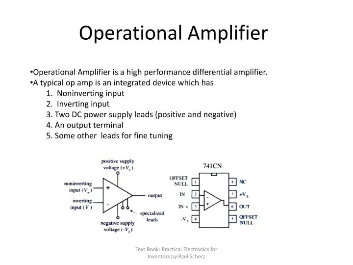
Operational Amplifier is a high performance differential amplifier. • A typical op amp is an integrated device which has 1. Noninverting input 2. Inverting input 3. Two DC power supply leads (positive and negative) 4. An output terminal 5. Some other leads for fine tuning Operational Amplifier Text Book: Practical Electronics for Inventors by Paul Scherz
Op amp is an integrated device consist of a large number of transistors, several resistors and a few capacitors • It has three stages : 1. A high input impedance differential amplifier. 2. a high gain voltage amplifier with a level shifter and 3. a low impedance output amplifier. Operational Amplifier Text Book: Practical Electronics for Inventors by Paul Scherz
Basic Operation: • If the inverting input V_ is more positive than the noninverting input V+ than the output voltage saturates towards the negative supply voltage -Vs. • If the noninverting input V+ is more positive than the inverting input V- then the output voltage saturates towards the positive voltage supply +Vs Operational Amplifier Text Book: Practical Electronics for Inventors by Paul Scherz
Basic Operation: • Op amp itself is not a special device until it is configured in special ways. • The output of the op amp can be controlled by feeding back the output to the inverting input. • The following is the figure of an inverting amplifier where the output of the op amp is fed back through a resistor RF to the inverting input. • Gain for this configuration is RF/Rin Operational Amplifier Text Book: Practical Electronics for Inventors by Paul Scherz
Ideal and Real op amp, some rules: • For an ideal op amp the open loop voltage gain is infinite. For a real op amp, the gain is typically 104 to 106 • Ideal input impedance infinite, real input impedance is between 106 ohm. • Ideal output impedance zero, real input impedance is between 10 to 1000 ohm. • Input terminal current for ideal op amp is zero whereas in reality it draws a very small amount of current which is in pico ampere range. Operational Amplifier Text Book: Practical Electronics for Inventors by Paul Scherz
Negative feedback and a special rule: • In negative feedback configuration an extra voltage (positive or negative) is fed back to the input. • If f is the fraction of the voltage fed back to the input then • Rule: in a negative feedback circuit whenever it sees a voltage difference between the inverting and non inverting input it sends a compensating voltage to the input to make the difference zero. Operational Amplifier Text Book: Practical Electronics for Inventors by Paul Scherz
Buffer (Unity gain amplifier) Operational Amplifier • Gain is 1 because no feed back or input resistors are used. • Gain=Vout/Vin=RF/Rin=1 • Application: It is used where circuit isolation is required (Very high input impedance) Text Book: Practical Electronics for Inventors by Paul Scherz
Inverting amplifier Operational Amplifier Text Book: Practical Electronics for Inventors by Paul Scherz
Noninverting amplifier Operational Amplifier V-=V+=Vin (Voltage divider rule) Text Book: Practical Electronics for Inventors by Paul Scherz
Summing amplifier Operational Amplifier But, So, When R1=R2=R3 Text Book: Practical Electronics for Inventors by Paul Scherz
Operational Amplifier Difference amplifier (since no current between inputs) Since, I1=I2 So, (Since V- = V+ ) If Text Book: Practical Electronics for Inventors by Paul Scherz
Operational Amplifier Integrator Since V+ is 0 so V- is 0 too (from negative feedback rule) By KVL IR+IC=0 Text Book: Practical Electronics for Inventors by Paul Scherz
Operational Amplifier Differentiator Since V+ is 0 so V- is 0 too (from negative feedback rule) By KVL IR+IC=0 Text Book: Practical Electronics for Inventors by Paul Scherz
Operational Amplifier Comparator • Essentially compares two signals • Output goes high when the input signal is greater than a reference signal. Text Book: Practical Electronics for Inventors by Paul Scherz
Operational Amplifier LM324/LM124 op amp IC Text Book: Practical Electronics for Inventors by Paul Scherz
A practical circuit using op amp 10K Text Book: Practical Electronics for Inventors by Paul Scherz