Download
1 / 15
170 likes | 401 Views
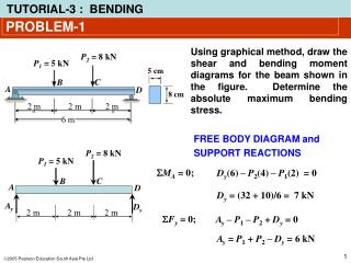
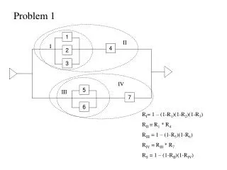
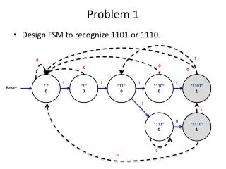
PROBLEM-1. State of stress at a p oin t is represented by the element shown. Determine the state of stress at the p oin t on another element orientated 30 clockwise from the position shown. PROBLEM-1. PROBLEM-1. PROBLEM-2.

E N D
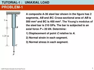
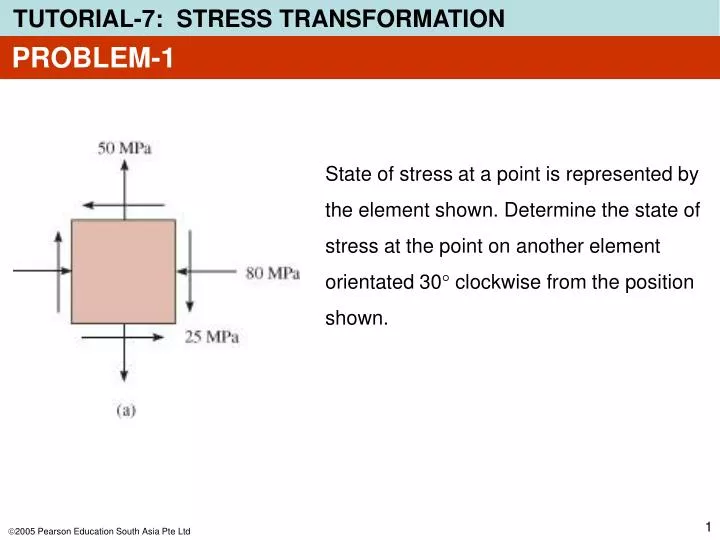
PROBLEM-1 State of stress at a point is represented by the element shown. Determine the state of stress at the point on another element orientated 30 clockwise from the position shown.
PROBLEM-2 State of plane stress at a point on a body is represented on the element shown. Represent this stress state in terms of • the maximum in-plane shear stress and associated average normal stress, and • the in-plane principal stress and its orientation.
PROBLEM-2 • The maximum in-plane shear stress and associated average normal stress. qs = 21.3o
PROBLEM-2 2. The in-plane principal stress and its orientation.
PROBLEM-2 Principal stress orientation. qp = – 23.7o
PROBLEM-3 Steel pipe has inner diameter of 60 mm and outer diameter of 80 mm. It is subjected to a torsional moment of 8 kN·m and a bending moment of 3.5 kN·m. Determine: • The maximum in-plane shear stress and associated average normal stress. • The in-plane principal stress and its orientation.
PROBLEM-3 Investigate a point on pipe that is subjected to a state of maximum critical stress. • Torsional and bending moments are uniform throughout the pipe’s length. • At arbitrary section a-a, loadings produce the stress distributions shown. • Point A undergoes maximum compressive stress and point B undegoes maximum tensile stress. • Thus, the critical point is at B.
PROBLEM-3 Maximum tensile stress at point B: Maximum shear stress at point B:
PROBLEM-3 • The maximum in-plane shear stress and associated average normal stress.
PROBLEM-3 2. The in-plane principal stress and its orientation. qp = – 33.1o
PROBLEM-4 Stress in Shafts Due to Axial Load, Bending Load and Torsion A shaft has a diameter of 4 cm. The cutting section shows in the figure is subjected to a compressive force of 2500 N, a bending moment of800 Nm and a torque of 1500 Nm. Determine: 1. The stress state of point A. 2. The principal stresses and its orientation
txy sx PROBLEM-4 1. The stress state at point A has been solved in Tutorial-6 Problem-3. The results are as follows Shear stress: txy= tA= 119.37 MPa Normal stress: sx= sA’ + sA” = (– 1.99 – 127.32) MPa = – 129.31 MPa
PROBLEM-4 2. The principal stress at point A and its orientation qp = – 30.78o