Download
1 / 33
360 likes | 382 Views
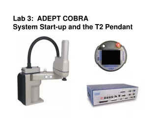
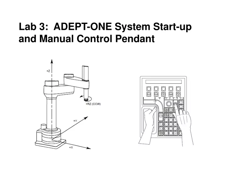
Lab 3: ADEPT-ONE System Start-up and Manual Control Pendant. ADEPT-ONE Programming Modes 1. World State (Cartesian) Joint Mode 3. Tool State Mode 4. FREE Mode. Cartesian X Y Z.

E N D
ADEPT-ONE Programming Modes • 1. World State (Cartesian) • Joint Mode • 3. Tool State Mode • 4. FREE Mode
Cartesian X Y Z The world coordinate system for a Cartesian robot is shown in Figure 4-5. If “X1” is selected, pressing the “+” speed bar will move the robot tool flange in the positive X direction. Pressing the “–” speed bar will move the flange in the negative X direction.
World State (Cartesian) World State: This is a cylindrical robot that will move in Cartesian Mode. When “world” state is selected, movement in the X, Y, or Z direction is parallel to an axis of the world coordinate system. Before the speed bars will move the robot, an axis of motion must be selected from the manual control buttons. The world coordinate system for a SCARA robot is shown in Figure 4-4. If “X1” is selected, pressing the “+” speed bar will move the robot tool flange in the positive X direction. Pressing the “–” speed bar will move the flange in the negative X direction.
Joint Mode Joint State When joint state is selected, movement is about the axis of the specified joint. Figure 4-8 shows an Adept SCARA robot with three rotational joints (joints 1, 2, and 4) and one translational joint (joint 3). Positive rotation of joints 1 & 2 is counter-clockwise as viewed from above. Positive rotation of joint 4 is clockwise as viewed from above. Positive movement of joint 3 is downward. Before the speed bars will move a joint, the correct joint must be selected from the manual control buttons. Different types of motion devices will have the different joint numbers assigned to their joints. When you first move an unfamiliar robot using joint state, set the monitor speed to 10 or lower, put the robot in a safe area, and carefully move the robot using the different joint numbers to verify how the MCP moves the robot. See the documentation for the motion devices you are using for details on their joint assignments.
Tool State Mode Tool State When “tool” state is selected, movement in the X, Y, or Z direction is along an axis of the tool coordinate system. The tool coordinate system is centered at the robot tool flange with the Z axis pointing away from the flange. The positive X axis is aligned with the center of the tool flange keyway. Before the speed bars will move the robot, an axis of motion must be selected from the manual control buttons. If “X1” is selected, pressing the “+” speed bar will move the robot tool flange in the positive X direction. Pressing the “–” speed bar will move the flange in the negative X direction. In a four-axis robot, positive rotation of the gripper is clockwise as viewed from above. Figure 4-6 shows the tool state for a four-axis SCARA robot.
FREE Mode Joint State When free state is selected, individual joints are freed from servo control, and the robot brakes (if any) are released.3 Unlike the other states, you can make multiple selections from the manual control buttons to free as many joints as required. In some cases, such as joints 1 & 2 on a SCARA robot, multiple joints are freed by selecting a single button. As soon as the “COMP/PWR” button is pressed, or another selection is made from the manual control buttons, all joints are placed back under servo control and will not move freely.
FREE Mode WARNING: As soon as a joint is selected from the manual control buttons, the related joint is free to move (in some cases, multiple joints may be freed up). In many cases the weight on the joint will be sufficient to move the joint and cause damage or harm. For example, when joint 3 on a SCARA or Cartesian robot is freed, the joint is free to fall to the end of its travel. In articulated robots, multiple links of the robot may be free to fall when a single joint is freed up. Be extremely careful when selecting a joint in free mode.
AdeptOne-MV Robot Manual • Chapter 4: Commissioning the System • This chapter covers commissioning, or putting into service, the Adept robot system. This includes • verifying that the installation is complete, starting and stopping the robot • 2. how to move the robot with the MCP. • verify that the E-Stop system, both Adept-supplied and customer-supplied equipment, is connected and working correctly.
Physical Connections Before turning on the controller and enabling High Power, make sure that the following cables are installed correctly. See Chapter 2 for installation instructions. • robot to power chassis • robot to controller • robot to Security Panel • controller to power chassis • controller to Security Panel • power chassis to Security Panel • VFP to controller, Security Panel and MCP Make sure you have installed proper safeguards and E-Stop circuits as described in Chapter 1 and Chapter 3.
4.3 VFP Operating Modes Adept robots have two different operating modes. The VFP incorporates a 2-position rotary key switch marked MANUAL and AUTO that controls whether the robot is operating in Manual or Automatic mode. For safety reasons, High Power is automatically disabled when the operating mode is changed.
Manual Operating Mode: In the MANUAL position of the keys witch, robot motion can be initiated only from the Manual Control Pendant (MCP). In Manual mode it is not possible to initiate a motion with the system keyboard. This protects the operator in the work cell from unexpected motions of the robot. In Manual mode the maximum speed of the Tool Center Point and the joints of the robot is reduced to 250 mm per second (10 ips). Also, the motors run at reduced torque. If the robot tries to move with a higher speed, sensors in the robot and the power amplifiers will detect this fault and turn off High Power to the power chassis. In Manual mode the contacts of the Customer Safety Barrier (Mute) are muted and the safety function of these contacts are disabled. This permits a skilled operator to enter the work cell while High Power is enabled.
Automatic Operating Mode The AUTO position of the operating key switch permits computer control of the robot. A program that is currently running the robot or motion device may cause it to move at times or along paths you may not anticipate. When the amber HIGH POWER light and the white PROGRAM RUNNING light on the VFP are illuminated, do not enter the work cell because the robot or motion device might move unexpectedly. WARNING: Impact Hazard! In Automatic mode no personnel are allowed to stay in the work cell. The robot can move at high speeds and exert considerable forces. CAUTION: The LAMP TEST button on the VFP allows you to check the HIGH POWER light and the PROGRAM RUNNING light on the VFP. Adept recommends checking the two lights periodically, prior to entry into the workcell. NOTE: The MCP can be used in Automatic (COMP) and in Manual (MAN) mode. For example, it is possible to calibrate the robot, or to enable High Power with the MCP in Automatic mode.
4.7 How to Start the Robot Enable High Power with the terminal 1. Turn on the power switches on the controller and the power chassis. 2. Set the VFP System Power switch to manual to turn on the power. 3. Verify that all Emergency-Stop switches are pulled out. 4. Press the “COMP/PWR” button on the COMP. 5. Type on the screen ENABLE POWER 6. The “HIGH POWER light should come on. 7. Next type CAL and wait for the self test program to run. WARNING: Impact Hazard! no personnel are allowed to enter or stay in the workcell. The robot can move at high speeds and exert considerable force.
4.7 How to Start the Robot Enable High Power with the MCP Mode 1. Turn on the power switches on the controller and the power chassis. 2. Set the VFP System Power switch into the position I, to turn on system power. 3. Verify that all Emergency-Stop switches are pulled out and all access doors to the workcell are closed. 4.. Set operating keyswitch to AUTO and the other keyswitch to LOCAL. 5. Press the “COMP/PWR” button on the MCP. 6. Press the blinking “HIGH POWER ON/OFF” button on the VFP within 10 seconds.
Calibration of the Robot with the MCP: The robot can be calibrated only when High Power is enabled and Automatic mode is selected. If the robot is in Manual mode, you must switch to Automatic mode. After changing the operating mode, the controller shuts off High Power automatically. See the instructions above to enable High Power again. 1. Set the VFP operating keyswitch to the AUTO position and verify that the other keyswitch is in the LOCAL position. If necessary, re-enable High Power. 2. Press the CMD soft button to display functions. 3. Press the soft button below the text CALIB in the display to start calibration. Once the robot is calibrated you can move the robot. If High Power is turned off after calibration is complete, you have to Enable Power again, but you do not have to calibrate. If system power is turned off at the VFP, then you must Enable Power and Calibrate.
Function Buttons The predefined function buttons have specific, system-wide functions assigned to them. These functions are covered in Chapter 3. The programmable function buttons are used in custom application programs, and their functions will vary depending upon the program being run.
Data Entry Buttons The “data entry” buttons are used to input data, normally in response to prompts that appear on the pendant display. The data entry buttons include, +/YES, –/NO, DEL, the numeric buttons (0-9), the decimal point, and the REC/DONE button. These buttons are similar to the numeric keypad on a standard keyboard.
The REC/DONE Button The REC/DONE button behaves like the Return or Enter key on a normal keyboard. When data entry is complete, pressing REC/DONE sends the entry to the controller. In many cases, applications programs have users press the REC/DONE button to signal that they have completed a task.
The DEL Button The DEL button acts like the backspace key on a normal keyboard. When data is being entered, it will appear on the pendant display. DEL will delete any characters that appear on the pendant display, but have not been entered using the REC/DONE button. Applications programs may also assign special functions to the DEL button.
2.3 Emergency Stop From the MCP To immediately halt program execution and turn off ARM POWER, press the emergency stop button on the MCP. This switch has the same effect as pressing the emergency stop button on the controller. If you are using the operator’s pendant, you may also release the arm power interlock switch to halt program execution and shut off ARM POWER. To re-enable arm power after pressing the MCP emergency stop button, turn the emergency stop button to the right (clockwise). The switch is spring loaded and will return to its normal position. If you are using the operator’s MCP, depress the palm switch. ARM POWER can now be reenabled by pressing the “COMP/PWR” button (mode control group), or by entering the ENABLE POWER command from the keyboard.
The Edit Function • The Display Function • The Clear Function • The CMD Function • Program Set Function
Predefined Function Buttons The Edit Function: (Change a Locations): The Edit function button allows editing of location variables and real variables that are used by V+ programs. The Display Function: The Display function button allows either the current joint values, the current world location, the system status, the digital I/O3 status, or the last error message to be displayed on the MCP. The Clear Error Function: If the MCP is in the “Pendant” position, or the system switch MCP.MESSAGES is enabled, error messages are sent to the MCP. When an error is sent to the MCP, the MCP will beep, display a blinking error message, and light the LED on the “CLR ERR” button. The CMD Function: The CMD function button displays the options AUTO START, CALIBRATE, STORE ALL, CMD1, and CMD2. Program Set Function: Using the prog set button, you may select a new program to execute, set the starting step number, set how many cycles of the program to perform, set the monitor speed, and start a memory resident application program.
Moving a Robot with the MCP Mode Control Buttons : The mode control buttons change the state being used to move the robot, switch control of the robot between the MCP and application programs, and enable ARM POWER (when necessary). The buttons are labeled in red.
Moving a Robot with the MCP Speed Bars The “speed bars” are used to control the robot’s speed and direction. The joint(s) that will move when the speed bars are pressed depends on the “state” selected with the MAN/HALT button. Press the speed bars with your left thumb. Pressing the speed bars near the outer ends will move the robot faster, pressing the speed bar near the center will move the robot slower.
Moving a Robot with the MCP Slow Button: The slow button selects between the two different speed ranges of the speed bars. When the slow button LED is lit, the slower speed range is selected.
Moving a Robot with the MCP World State When “world” state is selected, movement in the X, Y, or Z direction is parallel to an axis of the world coordinate system. Before the speed bars will move the robot, an axis of motion must be selected from the manual control buttons. If “X1” is selected, pressing the “+” speed bar will move the robot tool flange in the positive X direction. Pressing the “–” speed bar will move the flange in the negative X direction.
Moving a Robot with the MCP Caution: If you drive a joint past its limit or for example, the Z-axis onto the table, a current sensor will sense a stalled motor and the drive power will shut down like hitting an E-Stop. An error will be indicated on the pendant with an error light. You must then enable power, clear the error, then drive the joint in the opposite direction to prevent the error from setting again. DRIVE CAREFULLY
Moving a Robot with the MCP THE END