Download
1 / 16
160 likes | 270 Views
TIGERBOT MECHANICAL DESIGN. Kyle Backer (EE), Jeremy Jensen (ME), Matthew DeCapua (EE), Eric Walkama (ME), Mike Thomas (EE), Jonathan Cormier (CE), John Seybold (CE). 2 DOF in Head 4 DOF/Arm 1 DOF in Torso 6 DOF/ Leg. Overview. CHECKLIST. ~25.5” Tall (feet to shoulder)

E N D
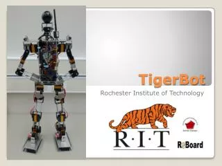
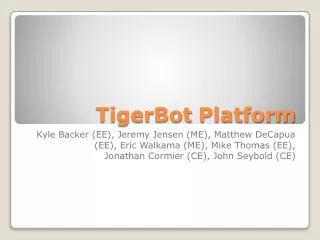
TIGERBOT MECHANICAL DESIGN Kyle Backer (EE), Jeremy Jensen (ME), Matthew DeCapua (EE), Eric Walkama (ME), Mike Thomas (EE), Jonathan Cormier (CE), John Seybold (CE)
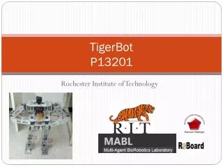
2 DOF in Head • 4 DOF/Arm • 1 DOF in Torso • 6 DOF/ Leg Overview
~25.5” Tall (feet to shoulder) • 10” Shoulder Width • 2.5” Torso Width BODY DIMENSIONS
4 Simple brackets for multiple servo mounting orientations • Side mount • Bottom mount • Large “C” bracket • Single plane dual axis rotation • Shoulder Rotation Side Mount Bottom Mount Large “C” Custom Servo Brackets Shoulder Rotation
Simple Aluminum rods, ¼” • Cut to length Height adjustability • Very cheap (~$7 per 6ft) • Integrates into standard servo brackets. Arm Assembly Custom Brackets Store bought Brackets Simple 6-32x1/2” machine screws for assembly LINKS & BRACKET INTEGRATION
Ball Bearing • Axial and Radial Loads • Low rotation friction • Ball Bearings are cheap • Reduce stress on servo horn • Increased hip Stiffness -Green Rotation -Gray Static HIP DESIGN
Leg Lift Squat T3 Push up T3 T2 Te Te T1 (cos(ϴ))+g1(L1/2)(cos(ϴ)) T2=(g2)(L2/2)(cos(ϴ))+(L2)(g3) T3~0 TORQUE REQUIREMENTS F F/2 F/2
ROBOARD SERVO SPECS • Standard size digital servo• Torque @7.4V: 35.0 kg-cm/486.0 oz-in• Speed: 0.11 sec/60º• Voltage: 6 to 7.4V • Weight: 70g TORQUE RESULTS
Breaking on fall • Easily and cheaply replaceable frame • Insufficient torque • Adjustable height • Wire routing • Open skeleton design, adjustable chest volume • Boards shorting • Large board spacing, easy addition of insulation layer in chest Mechanical System Risks