Download
1 / 22
240 likes | 739 Views
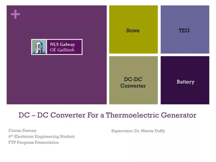
Stove. TEG. DC-DC Converter. Battery. DC – DC Converter For a Thermoelectric Generator. Supervisor: Dr. Maeve Duffy. Ciaran Feeney 4 th Electronic Engineering Student FYP Progress Presentation. Presentation Overview. Project overview Progress to date Future work and timeline

E N D
Stove TEG DC-DC Converter Battery DC – DC Converter For a Thermoelectric Generator Supervisor: Dr. Maeve Duffy Ciaran Feeney 4th Electronic Engineering Student FYP Progress Presentation
Presentation Overview • Project overview • Progress to date • Future work and timeline • Questions
Project Overview • Researchers in Trinity College Dublin are developing a energy harvesting system for use in developing countries. • Generate electricity using a Thermoelectric Generator(TEG) from excess heat produced during the cooking process. • Store energy generated in a battery • Use stored power in low power applications • This project focuses on providing an impedance match between the source and load using a DC-DC Converter and Microcontroller
Progress To Date • Thermoelectric generator operation understood • Battery charge and discharge profile established • DC-DC converter Topology determined • Basic analysis of 1st SEPIC DC-DC converter circuit complete • Suitable Microcontroller found • Website online and blog regularly updated
Thermoelectric Generator Single Thermoelectric Couple Full Thermoelectric Generator
Thermoelectric Generator Equivalent TEG Circuit Model
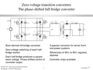
DC-DC Converter • Require DC-DC converter that can provide an output voltage above and below input voltage • Variation of Buck Boost topology decided upon • SEPIC DC-DC Converter • Non-inverting output • Isolation between output and input terminals due to coupling capacitor
DC-DC Converter SEPIC Topology SEPIC Converter 1st Prototype Chosen Components
DC-DC Converter Input Voltage 4V Matched Voltage 2V Output Voltage .846V Duty Cycle 41.8% Efficiency 71.4% Resistive Load
DC-DC Converter • Redesigned SEPIC Converter • Switching frequency is now 80kHz • Reduces size of components • Reduces cost • Diode Replaced by MOSFET • Circuit Components
DC-DC Converter • New Design Replacing diode with MOSFET • Design includes Equivalent Series Resistances for components
Microcontroller • Required characteristics • PWM (Pulse Width Modulation) • Analog Input pins • Low power consumption • Low cost • Easily programmable • Chosen Controller – Arduino Uno • Fulfills all of the above criteria • Cost €24.31 • Abundance of information available online
Future Work • MPPT • Initial Investigation shows that load current should be maximized as the battery can be viewed as a purely voltage source. • Preliminary investigation into current sensors reveals that a hall effect sensor should be used instead of a current sense resistor. • Sensor to be placed in series with battery • A hall effect sensor has been singled out for further investigation The Allegro Microsystems Current Sensor • Rated for 5A • Low series resistance 1.2mΩ • Cost low €6.54 • 185mV per Amp
Future Work • Charge Algorithm • Constant current to 3.6V • Constant voltage of 3.6V until charge cut off current is reached or 30 minutes has elapsed • Voltage to be monitored across battery • Yet to be decided whether a constant voltage will be applied • Researchers in Trinity College Dublin to decide this
Future Work • Implementation of Circuit with • Thermoelectric Generator • Microcontroller implementing MPPT • Simulated cooking profile/Actual cooking duration • Battery • Efficiency analysis over cooking profile • Identify were improvements can be made
Timeline • Efficiency Analysis • MPPT & Charge • Algorithm • 1st Draft of Mock Circuit Analysed and Deficiencies located. Circuit Optimised to minimise deficiencies. • 16th of January 2011 • Final Circuit and Testing • MPPT & Charge Algorithm decided upon and completed. • 14th of February 2011 • Bench Demonstration • Finished circuit completed incorporating MPPT and charge algorithm. Circuitry tested over full charge and discharge cycle with TEG and battery. • 7th of March 2011 • Week of the 14th of March 2011 • 1st of April 2011 • Final Thesis