Download

1 / 44
450 likes | 462 Views
Transmission Media. A transmission medium can be broadly defined as anything that can carry information from a source to a destination. For example, the transmission medium for two people having a dinner conversation is the air. Figure 7-2. The McGraw-Hill Companies, Inc., 1998.

E N D
A transmission medium can be broadly defined as anything that can carry information from a source to a destination. • For example, the transmission medium for two people having a dinner conversation is the air.
Figure 7-2 The McGraw-Hill Companies, Inc., 1998 WCB/McGraw-Hill
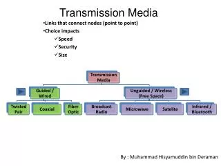
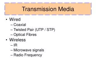
Guided media, which are those that provide a conduit from one device to another. Unguided media transport electromagnetic waves without using a physical conductor.
Figure 7-3 The McGraw-Hill Companies, Inc., 1998 WCB/McGraw-Hill
Twisted-Pair Cable Figure 7-4 and 7-5 Twisted Pair and Coax use metallic(Copper) conductors that accept and transport the signals in the form of Electrical Current. The McGraw-Hill Companies, Inc., 1998 WCB/McGraw-Hill
Figure 7-6 Effect of Noise on Parallel Lines The McGraw-Hill Companies, Inc., 1998 WCB/McGraw-Hill
Figure 7-7 Noise on Twisted-Pair Lines The McGraw-Hill Companies, Inc., 1998 WCB/McGraw-Hill
Figure 7-8 Unshielded Twisted-Pair Cable The McGraw-Hill Companies, Inc., 1998 WCB/McGraw-Hill
Figure 7-10 Shielded Twisted-Pair Cable • Metal casing prevents the penetration of electromagnetic noise. • Eliminate the phenomenon , called CROSSTALK The McGraw-Hill Companies, Inc., 1998 WCB/McGraw-Hill
Advantages : 1. Cheaper2. Less susceptible to electrical interference caused by nearby equipment or wires.3. In turn are less likely to cause interference themselves.4. Because it is electrically "cleaner", STP wire can carry data at a faster speed.Disadvantages : 1. STP wire is that it is physically larger and more expensive than twisted pair wire.
Coaxial Cable Figure 7-11 and 7-12 The McGraw-Hill Companies, Inc., 1998 WCB/McGraw-Hill
Two kinds of coaxial cable • One kind, 50-ohm cable, is commonly used when it is intended for digital transmission from the start. • The other kind, 75-ohm cable, is commonly used for analog transmission and cable television. • Cable TV operators began to provide Internet access over cable, which has made 75-ohm cable more important for data communication.
High bandwidth • Excellent noise immunity. • The bandwidth possible depends on the cable quality and length. • Used within the telephone system, cable television and MAN • For long-distance lines, but have now replaced by fiber optics on long distance routes.
Optical Fiber Cable Optical Fiber is a glass or plastic cable that accept and transport the signals in the form of Light. • Advantages: • Noise Resistance • Less Signal Attenuation • Higher BW • Disadvantages: • Cost • Installation/Maintenance • Fragility(Broken Wire)
7-2 UNGUIDED MEDIA: WIRELESS Unguided media transport electromagnetic waves without using a physical conductor. This type of communication is often referred to as wireless communication.
Figure 7-1 Electromagnetic Spectrum The McGraw-Hill Companies, Inc., 1998 WCB/McGraw-Hill
Figure 7.17 Electromagnetic spectrum for wireless communication
Note Radio waves are used for multicast communications, such as radio and television. They can penetrate through walls. Use Omni directional antennas
Note Microwaves are used for unicast communication such as cellular telephones and wireless LANs. Higher frequency ranges cannot penetrate walls. Use directional antennas - point to point line of sight communications.
Note Infrared signals can be used for short-range communication in a closed area using line-of-sight propagation.
Attenuation • Means loss of energy -> weaker signal • When a signal travels through a medium it loses energy overcoming the resistance of the medium • Amplifiers are used to compensate for this loss of energy by amplifying the signal.
Measurement of Attenuation • To show the loss or gain of energy the unit “decibel” is used. dB = 10log10P2/P1 P1 - input signal P2 - output signal
Example 3.26 Suppose a signal travels through a transmission medium and its power is reduced to one-half. This means that P2 is (1/2)P1. In this case, the attenuation (loss of power) can be calculated as A loss of 3 dB (–3 dB) is equivalent to losing one-half the power.
Example 3.27 A signal travels through an amplifier, and its power is increased 10 times. This means that P2 = 10P1 . In this case, the amplification (gain of power) can be calculated as
Example 3.28 One reason that engineers use the decibel to measure the changes in the strength of a signal is that decibel numbers can be added (or subtracted) when we are measuring several points (cascading) instead of just two. In Figure 3.27 a signal travels from point 1 to point 4. In this case, the decibel value can be calculated as
Example 3.29 Sometimes the decibel is used to measure signal power in milliwatts. In this case, it is referred to as dBm and is calculated as dBm = 10 log10 Pm , where Pm is the power in milliwatts. Calculate the power of a signal with dBm = −30. Solution We can calculate the power in the signal as
Distortion • Means that the signal changes its form or shape • Distortion occurs in composite signals • Each frequency component has its own propagation speed traveling through a medium. • The different components therefore arrive with different delays at the receiver. • That means that the signals have different phases at the receiver than they did at the source.
Noise • There are different types of noise • Thermal - random noise of electrons in the wire creates an extra signal • Crosstalk - same as above but between two wires. • Impulse - Spikes that result from power lines, lighning, etc. • Induced
Signal to Noise Ratio (SNR) • To measure the quality of a system the SNR is often used. It indicates the strength of the signal wrt the noise power in the system. • It is the ratio between two powers. • It is usually given in dB and referred to as SNRdB.
Example 3.31 The power of a signal is 10 mW and the power of the noise is 1 μW; what are the values of SNR and SNRdB ? Solution The values of SNR and SNRdB can be calculated as follows:
Example 3.32 The values of SNR and SNRdB for a noiseless channel are We can never achieve this ratio in real life; it is an ideal.