Download
1 / 9
90 likes | 178 Views
DAQ Update. DAQ Status. DAQ was running successfully and stably in ’07 beam time Trigger bus scheme has proven to be very flexible Added additional delayed trigger during beam time Event rate of 6 Hz ( m e g ) + ~10 Hz calibration events can be handled easily

E N D
DAQ Status • DAQ was running successfully and stably in ’07 beam time • Trigger bus scheme has proven to be very flexible • Added additional delayed trigger during beam time • Event rate of 6 Hz (meg) + ~10 Hz calibration events can be handled easily • Max. DAQ rate now is 30 Hz, 50 Hz with firmware update • Dead time will be reduced by multi-event buffering through firmware update • DAQ rate will be even higher with DRS4 (no calibration necessary) • DAQ rate was 0.6 TB/day (7 MB/sec) • Reduction from 9 MB/event to <1 MB/event • Further reduction to ~50% by gzip compression • 100 TB disk available for 2008
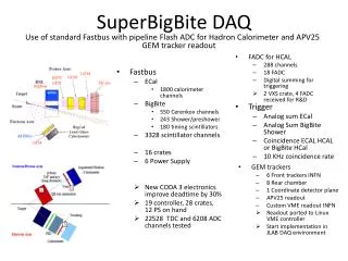
DAQ scheme trigger & trigger type & event # LSB busy TRG1 TRG2 TRG3 TRG9 DRS4 DRS5 DRS6 DRS7 DRS8 internal trigger & busy SYSTEM01 SYSTEM02 SYSTEM03 SYSTEM04 SYSTEM05 SYSTEM06 SYSTEM07 SYSTEM08 SYSTEM09 Event Builder • Front-end synchronization: • Trigger sent to all front-ends • Trigger type & event #LSB • Busy is wired-or of all FE • Check of event #LSB at event builder • Flexible trigger bus • Added delayed trigger during beamtime without H/W modification • 2nd level trigger possible in future SYSTEM Logger
DRS4 design • DRS2 used 2007 successfully for all ~3000 channels, but remaining issues • Temperature dependencies (solved by DRS3) • Poor clock pulse (solved by DRS3) • “Ghost pulse” problem (will be solved by DRS4) • DRS4 design • started Jan. 2008 • fixes “ghost pulse” problem, higher bandwidth, smaller package • integrated PLL • daisy-chaining of channels allows 1.6 GHz 3.2 GHz sampling speed (if needed) • Time plan • finish design: end of March ’08 • chip production: April – June ’08 • mezzanine board prototype: May ’08 • mass production: July/August ’08 • replace DRS2 by DRS4 as boards become available
DRS3 clock (last night ’07, 64 chn.) LVDS Clock DRS3 chip (differential input) R DRS3 clock signal DRS2 clock (‘07 beam time) LVDS Clock R DRS2 chip (single ended input)
Solution: Clear before write write clear “Ghost pulse” problem R After sampling a pulse, some residual charge remains in the capacitors on the next turn and can mimic wrong pulses “Ghost pulse” 2% @ 2 GHz
On-chip PLL Internal PLL Vspeed PLL Reference Clock (0.2-2 MHz) External PLL • On-chip PLL should show smaller phase jitter • If <100ps, no clock calibration required • fclk = fsamp / 2048 ~200 psec R. Paoletti, N. Turini, R. Pegna, MAGIC collaboration
Daisy-chaining of channels Domino Wave Generation • DRS4 can be partitioned in 8x1024 cells or 4x2048 cells • Smaller chip package of DRS4 allows 4 chips/mezzanine instead 2 DRS2 • Running with 2048 cell channels allow sampling speed of 1.6 GHz * 2 = 3.2 GHz with current trigger latency timing accuracy should improve ~2x • Implement if necessary Channel 0 – 1024 cells Channel 1 – 1024 cells Channel 2 – 1024 cells Channel 3 – 1024 cells Channel 4 – 1024 cells Channel 5 – 1024 cells Channel 6 – 1024 cells Channel 7 – 1024 cells