Download
1 / 31
390 likes | 562 Views
BACtalk Systems Installation and Commissioning Training Course. Course Goals and Objectives. Ethernet Networks Cabling / Addressing MS/TP Networks Cabling / Addressing / LAN Tuning VisualLogic Controllers Installation / Power / Inputs / Outputs BCMs/ VLX / MSTP Repeaters / FST-100

E N D
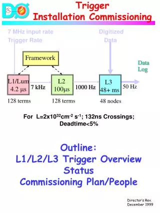
BACtalk SystemsInstallation and CommissioningTraining Course
Course Goals and Objectives • Ethernet Networks • Cabling / Addressing • MS/TP Networks • Cabling / Addressing / LAN Tuning • VisualLogic Controllers • Installation / Power / Inputs / Outputs • BCMs/ VLX / MSTP Repeaters / FST-100 • Installation / Configuration / Testing • Troubleshooting • Power / Communications / Inputs & Outputs
VLC’s Terminals Identification • Power supply terminals <num> - 24VAC • Ground terminals <num> - GND (for power and BO) • Common terminals <num> - COM (Separate for IN & AO) • Universal inputs <num> - IN <ID> • Binary outputs (BOs) <num> - BO <ID> • Analog outputs (AOs) <num> - AO <ID> • MS/TP LAN communications <num> - DATA + • <num> - DATA – • 24VDC source <num> - 24VDC • No Connection <num> - NC
Power Wiring – Half Wave Devices Single Device:
Power Wiring – Half Wave Devices Multiple devices powered from the same transformer:
AC - Rectification • Do not share transformers for Half and Full Wave Devices….!!!! • BTI and MSTP Repeater are Full Wave, all others are Half Wave devices • Check for other field devices before connecting them…
Inputs Termination 4-20 ma Pulse
Inputs Jumper / Dips Setting Jumpers Dips
Outputs Termination Binary Analog
MS/TP Network – Cabling • EIA-485 signaling standard • High quality tranciever; exerts only ¼ unit load on MS/TP • 9.6, 19.2, 38.4, or 76.8Kbps (configured at global controller). • Shielded Twisted Pair 18-22 AWG • Segment Length = 4000 ft • Use of MS/TP repeater increases number of segments and not number of devices. • Maximum of 3 repeaters between each device. • Matched terminating resistors required at each end of segment bus wired • across (DATA+) and (DATA–). Use matched resistors rated 80-120 ohm ¼W • ±5%. • Never ground both ends of a shield • Do not ground the MS/TP shield using a VLC terminal.
Recommended Cable for MSTP • Characteristic impedance between 100 and 130 ohms. • Distributed capacitance between 2 conductors shall be less than 100pF per meter (30 pF per foot). • Distributed capacitance between conductors and shield shall be less than 200 pF per meter (60 pF per foot). • Foil or braided shields are acceptable. • Connect Air : W241P-2544 • Belden : 9841 (1-pair/24awg, 12.8pF 120ohm)
MS/TP Network – Addressing • BACnet MS/TP LAN supports a maximum of 255 devices – addressed 0 ~ 254 • BACnet reserves address 255 • MS/TP = Master Slave / Token Passing • Maximum of 128 masters – addressed 0 ~ 127 • All Alerton devices are Masters • Alerton specification – 64 VLCs per LAN • Alerton uses ¼ unit load EIA-485 transceivers
MS/TP Network – Addressing • MAC address in the range 0–127 (Master Devices) • Using switch 8 will cause the VLC to be a slave device (not recommended) • 0 and 127 are often reserved for the BACtalk global controller
BACtalk Control Modules (BCMs) • High-performance, modular global controllers • BCm-PWS + 7 modules • Flexible, scalable • DIN rail mount • Requires 6-inch deep panel enclosure • NOT Hot Swappable! • Each have unique device instance except PWS and MDM • 8 MB Flash ; 32 MB RAM
Architecture • BACnet Ethernet and BACnet/IP • Connect to LAN via Ethernet Switch • Remote access via BCM modem module • Gateway modules available… • BCM-TUX • BCM-MODBUS • BCM-HOTEL
Configuration • Unique software device instance for each module except PWS and MDM • DI set through Hyper Terminal using NULL Modem Cable. • Use CAT-5 or better for Ethernet • Always use a switch with all devices supporting 100Mbps • Maximum Ethernet length 100m (328ft) • Does not implement internal crossover
Boot Loader and ROC files • System boot code is factory loaded and cannot be changed and configured • Real Time Operating Code (ROC: *.OMF / *.BIN) factory loaded with software up gradable for latest firmware revisions. • DDC files (*.bd3) ; compiled version
VisualLogic Controllers – Input Scaling • Electrical Characteristics of VLC Inputs • Resolution of Input Signal • Scaling • Tables of Standard Input Ranges
VisualLogic – VLC Device Settings • Device Settings for a VLC… • Inputs • Scaled Two-Point Utility • Filtering • Jumper/DIP Switch Settings
VisualLogic – VLC Device Settings • Review the Device Settings for a VLC… • Priority Arrays • Binary Outputs • Analog Outputs • Analog Values
BTI-100 – Global Controller • 10/100 Ethernet NIC • 1 MS/TP LAN • 1 Serial Port (PTP) • External Modem Only • Two Batteries • Diagnostic LEDs • 24vAC – Half Wave
VLX – Building Controller • 10/100 Ethernet NIC • 1 MS/TP LAN – supports max 10 VLCs • Expandable I/O – supports up to 8 EXPs • Coin Cell Battery • 24vAC – Half Wave
VLX – EXP Modules • EXP-1048 • 10 Universal Inputs • 4 Binary Outputs with Hand-Off-Auto Switches • 8 Analog Outputs with H-O-A Switches and manual potentiometer • EXP-10120 • 10 Universal Inputs • 12 Binary Outputs with H-O-A Switches • EXP-2200 • 22 Universal Inputs
VLX – EXP Modules • Configuration of VLX • Configuration of EXP Modules • Inputs • Outputs
VLX – EXP Modules • Inputs • Scaling • Out of Service • Outputs • Backup Mode • Out of Service • HOA Switches
Troubleshooting • Review Troubleshooting Guidelines… • Power • Inputs • Outputs • Communications