Download

1 / 14
140 likes | 358 Views
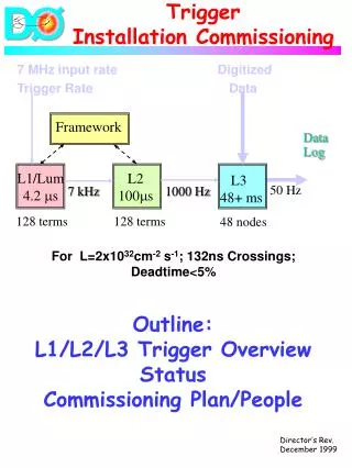
SVT Installation and Commissioning. Takashi Maruyama, SLAC HPS Collaboration Meeting June 16-18, 2014. SVT Installation . SVT. 58”. Now 85.00” . Now 85.00”. 50.1 “. SVT Installation Steps:. Separate top/bottom ECal and move downstream Remove ECal vacuum chamber. 45 cm.

E N D
SVT Installation and Commissioning Takashi Maruyama, SLAC HPS Collaboration Meeting June 16-18, 2014
SVT Installation SVT 58” Now 85.00” Now 85.00” 50.1 “
SVT Installation Steps: Separate top/bottom ECaland move downstream Remove ECal vacuum chamber 45 cm 2. Remove upstream beam pipe, PS vacflange; move Frascatiupstream 3. Set up survey instruments upstream and downstream of PS vac chamber Does the instrument fit in 45 cm?
SVT Installation Steps: • 4. Put SVT box on table and slide into PS vac chamber and bring to correct Z SVT 5. With surveyors, position SVT horizontally and vertically at downstream end; ditto upstream end. 6. Lock SVT Box in place 7. Survey location of PS vac inner surfaces, SVT box outer surfaces, SVT fiducials, check points.
SVT Installation Steps: 8. Install SVT vac box 9. Connect mover and target rods. Set hard stops and limit switches. Verify movers work. Check alignment with survey. 10. Connect cooling lines and test 11. Connect data/power cables and test12. Remove upstream table; restore upstream Frascati position. 13. Restore vac connections: Upstream Beampipe, EcalVac chamber.14. Pump down and Test Vacuum 15. Leave the SVT L1-3 at fully retracted position 16. Test cooling and data/power in vac 17. Replace Ecal and test As the linear stage moves, the limit switches may need adjustments.
Survey Information on the vacuum chamber Survey information wrt the straight-through beamline. • X position of vac chamber wall on beam’s right at upstream and downstream ends • Y position of vac chamber wall on bottom surface at upstream and downstream ends • Z position of the upstream flange mating surface at 4 corners. Vac chamber z z × y z y z × 8.85 cm Straight-through beam line
SVT Alignment • Alignment spheres: • Two at the top and one at the bottom of the base plate upstream and downstream. • End of the top and bottom rods. Adjustment screws:
SVT Commissioning SVT Commissioning will be performed under the following conditions, SVT Protection Collimator is in the 3 mm gap and the FSD system is working. SVT Layer 1 is retracted to 3 mm from the beam. SVT bias voltage is set to 60 V. • Efficiency is nearly 100% and high voltage punch-through damage to the front-end electronics can be avoided. SVT Chiller is running and temperature interlock is working.
Slow Control Power to the front end and flange boards High voltage bias Hybrid power Hybrid and front end board temperatures Chiller temperature
SVT Calibration Extraction of the pedestals and noise for each of the 23004 channels Extraction of the gains and offsets Runs at different t0 values to study the pulse shape SVT calibration can be done without beam, but it will be repeated with beam to make sure there is no beam-related anomalies.
Timing in the SVT Correctly timed in hits • Well controlled latency scan • Single cluster trigger (or an OR of top & bottom) • Low beam current to get single Ecalclusters for good reference time and no background • No pile-up pulse shape cuts in SVT (noise hits should be few) • Take runs with latency at 50-75ns steps Background ECal – SVT hit time (Ecal time above uses MC truth time ) We are producing these scans with MC to check (Omar)
Online monitor Occupancy Shaper signal samples Data rate DAQ Errors Occupancies from Test Run
Event display and hit efficiency Find tracks Efficiency for finding hits on tracks should be >99%
Conclusions • SVT installation procedure is being developed. • Details still need more work. • If we have to extract L1-3 for repair, how can we do that? • If we have to extract L4-6, is it possible to extract from downstream? • SVT alignment and survey need more attention. • Software for SVT commissioning are being developed. • Slow control • Software for Timing-in • On-line monitor • Event display