Download
1 / 47
470 likes | 489 Views
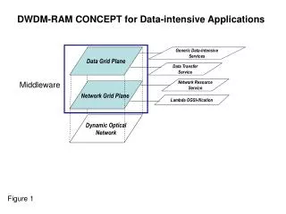
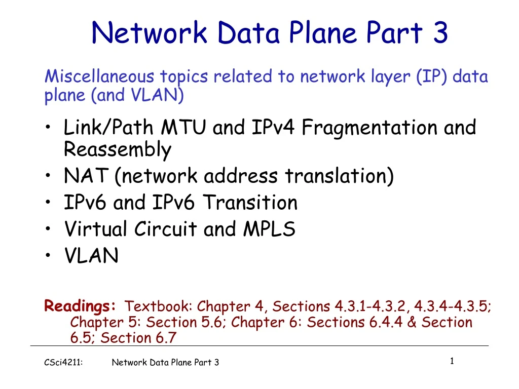
Network Data Plane Part 3. Miscellaneous topics related to network layer (IP) data plane (and VLAN) Link/Path MTU and IPv4 Fragmentation and Reassembly NAT (network address translation) IPv6 and IPv6 Transition Virtual Circuit and MPLS VLAN

E N D
Network Data Plane Part 3 Miscellaneous topics related to network layer (IP) data plane (and VLAN) • Link/Path MTU and IPv4 Fragmentation and Reassembly • NAT (network address translation) • IPv6 and IPv6 Transition • Virtual Circuit and MPLS • VLAN Readings: Textbook: Chapter 4, Sections 4.3.1-4.3.2, 4.3.4-4.3.5; Chapter 5: Section 5.6; Chapter 6: Sections 6.4.4 & Section 6.5; Section 6.7 CSci4211: Network Data Plane Part 3
ICMP protocol • error reporting • router “signaling” Transport layer: TCP, UDP IP protocol • addressing conventions • Datagram format • packet handling conventions Routing protocols • path selection • RIP, OSPF, BGP forwarding table Data Link layer (Ethernet, WiFi, PPP, …) Physical Layer (SONET, …) IP Forwarding & IP/ICMP Protocol Network layer CSci4211: Network Data Plane Part 3
IP protocol version number 32 bits total datagram length (bytes) header length (bytes) type of service head. len ver length for fragmentation/ reassembly fragment offset “type” of data flgs 16-bit identifier max number remaining hops (decremented at each router) upper layer time to live Internet checksum 32 bit source IP address 32 bit destination IP address upper layer protocol to deliver payload to E.g. timestamp, record route taken, specify list of routers to visit. Options (if any) how much overhead with TCP? • 20 bytes of TCP • 20 bytes of IP • = 40 bytes + app layeroverhead data (variable length, typically a TCP or UDP segment) IP Datagram Format CSci4211: Network Data Plane Part 3
Fields in IP Datagram • IP protocol version: current version is 4, IPv4, new: IPv6 • Header length: number of 32-bit words in the header • Type of Service: • 3-bit priority,e.g, delay, throughput, reliability bits, … • Total length: including header (maximum 65535 bytes) • Identification: all fragments of a packet have same identification • Flags: don’t fragment, more fragments • Fragment offset: where in the original packet (count in 8 byte units) • Time to live: maximum life time of a packet • Protocol Type: e.g., ICMP, TCP, UDP etc • IP Option: non-default processing, e.g., IP source routing option, etc. CSci4211: Network Data Plane Part 3
network links have MTU (max.transfer size) - largest possible link-level frame. different link types, different MTUs large IP datagram divided (“fragmented”) within net one datagram becomes several datagrams “reassembled” only at final destination IP header bits used to identify, order related fragments IP Fragmentation & Reassembly: Why fragmentation: in: one large datagram out: 3 smaller datagrams reassembly CSci4211: Network Data Plane Part 3
IP Fragmentation & Reassembly: How • An IP datagram is chopped by a router into smaller pieces if • datagram size is greater than network MTU • Don’t fragment option is not set • Each datagram has unique datagram identification • Generated by source hosts • All fragments of a packet carry original datagram id • All fragments except the last have more flag set • Fragment offset and Length fields are modified appropriately • Fragments of IP packet can be further fragmented by other routers along the way to destination ! • Reassembly only done at destination host (why?) • Use IP datagram id, fragment offset, fragment flags. Length • A timer is set when first fragment is received (why?) CSci4211: Network Data Plane Part 3
length =1500 length =1500 length =4000 length =1040 ID =x ID =x ID =x ID =x fragflag =0 fragflag =1 fragflag =1 fragflag =0 offset =185 offset =0 offset =0 offset =370 One large datagram becomes several smaller datagrams IP Fragmentation and Reassembly: Exp Example • 4000 byte datagram • MTU = 1500 bytes • offset in the second fragment: 185x8=1480 (why not 1500 bytes =length?) • offset in the third fragment: 370x8=2960 Except for last fragment, IP fragment payload size (i.e., excluding IP header) must be multiple of 8! CSci4211: Network Data Plane Part 3
length =4000 ID =x fragflag =0 offset =0 Quiz: Calculating length & Offset Example • 4000 byte datagram • MTU = 1500 bytes MTU = 1500 bytes MTU = 900 bytes A B CSci4211: Network Data Plane Part 3
length = 900 length = 900 length = 900 length =620 length = 620 length = 160 ID =x ID =x ID =x ID =x ID =x ID =x fragflag =0 fragflag =1 fragflag =1 fragflag =1 fragflag =1 fragflag =1 offset = 480 offset =370 offset =110 offset = 295 offset = 185 Offset = 0 Answer CSci4211: Network Data Plane Part 3
used by hosts, routers, gateways to communication network-level information error reporting: unreachable host, network, port, protocol echo request/reply (used by ping) network-layer “above” IP: ICMP msgs carried in IP datagrams ICMP message: type, code plus first 8 bytes of IP datagram causing error ICMP: Internet Control Message Protocol TypeCodedescription 0 0 echo reply (ping) 3 0 dest. network unreachable 3 1 dest host unreachable 3 2 dest protocol unreachable • 3 dest port unreachable 3 4datagram too big 3 6 destnetwork unknown 3 7 desthost unknown 4 0 source quench (congestion control - not used) 5 0,1 redirect for network/host 8 0 echo request (ping) 9 0 route advertisement 10 0 router solicitation 11 0 TTL expired 12 0 bad IP header CSci4211: Network Data Plane Part 3
ICMP Message Transport & Usage • ICMP messages carried in IP datagrams • Treated like any other datagrams • But no error message sent if ICMP message causes error • Message sent to the source • 8 bytes of the original header included • ICMP Usage (non-error, informational): Examples • Testing reachability: ICMP echo request/reply • ping • Tracing route to a destination: Time-to-live field • traceroute • Path MTU discovery (see next slide for more details) • Don’t fragment bit • IP redirect (for hosts only): inform hosts of better routes CSci4211: Network Data Plane Part 3
ICMP and Path MTU (RFC 1191) When a router is unable to forward a datagram, because it exceeds the MTU of the next-hop network and its “Don't Fragment” bit is set, the router is required to • return an ICMP “Destination Unreachable” message (type 3) to the source of the datagram, with code 4, indicating ”Fragmentation required and DF flag set". To support Path MTU Discovery, the router MUST • include the MTU of that next-hop network in the low-order 16 bits of the ICMP header field that is labelled "unused" in the ICMP specification. • The high-order 16 bits remain unused, and MUST be set to zero. CSci4211: Network Data Plane Part 3
NAT (Network Address Translation)A fix to limited IPv4 address space: rest of Internet local network (e.g., home network) 10.0.0.0/24 10.0.0.1 10.0.0.4 10.0.0.2 138.76.29.7 10.0.0.3 datagrams with source or destination in this network have 10.0.0.0/24 address for source, destination (as usual) alldatagrams leaving local network have same single source NAT IP address: 138.76.29.7,different source port numbers CSci4211: Network Data Plane Part 3
NAT (Network Address Translation) motivation: local network uses just one IP address as far as outside world is concerned: • range of addresses not needed from ISP: just one IP address for all devices • can change addresses of devices in local network without notifying outside world • can change ISP without changing addresses of devices in local network • devices inside local net not explicitly addressable, visible by outside world (a security plus) CSci4211: Network Data Plane Part 3
3 1 2 4 S: 10.0.0.1, 3345 D: 128.119.40.186, 80 S: 138.76.29.7, 5001 D: 128.119.40.186, 80 1:host 10.0.0.1 sends datagram to 128.119.40.186, 80 2:NAT router changes datagram source addr from 10.0.0.1, 3345 to 138.76.29.7, 5001, updates table S: 128.119.40.186, 80 D: 10.0.0.1, 3345 S: 128.119.40.186, 80 D: 138.76.29.7, 5001 NAT (Network Address Translation) NAT translation table WAN side addr LAN side addr 138.76.29.7, 5001 10.0.0.1, 3345 …… …… 10.0.0.1 10.0.0.4 10.0.0.2 138.76.29.7 10.0.0.3 4:NAT router changes datagram dest addr from 138.76.29.7, 5001 to 10.0.0.1, 3345 3:reply arrives dest. address: 138.76.29.7, 5001 CSci4211: Network Data Plane Part 3
IPv6: Motivation • initial motivation: 32-bit address space soon to be completely allocated. • additional motivation: • header format helps speed processing/forwarding • header changes to facilitate QoS IPv6 datagram format: • fixed-length 40 byte header • no fragmentation allowed --- hosts must perform path MTU discovery to learn about path MTU! CSci4211: Network Data Plane Part 3
Simplified Design of IPv6 Longer addressing space pri ver flow label Fix size IP Header hop limit payload len next hdr source address (128 bits) Can have one or more extension header fields destination address (128 bits) No checksum operation data No fragmentation 32 bits End hosts must perform path MTU discovery (using ICMP) per destination before sending any data! 2001:0db8:85a3:0000:0000:8a2e:0370:7334 CSci4211: Network Data Plane Part 3
? ? www.apnic.net IPv4 Application IPv6 TCP/UDP IPv4 IPv6 Link IPv6 Transition • Dual stack hosts • Two TCP/IP stacks co-exists on one host • Supporting IPv4 and IPv6 • Client uses whichever protocol it wishes CSci4211: Network Data Plane Part 3
IPv6 Header IPv6 Header IPv6 Header Data Data Data IPv4 Network IPv6 IPv6 tunnel IPv4 Header IPv6 Transition (cont’d) • IPv6 tunnel over IPv4 CSci4211: Network Data Plane Part 3
IPv6 tunnels over IPv4 provides an example of the general way that one type of networks can be used to support another type of networks to, e.g., support incremental deployment of a new protocol, accommodate the co-existence of multiple (heterogeneous) networks, or implement “network virtualization” (e.g., a “private network” running on top of a public Internet) IP-in-IP tunnels IPv6-in-IPv4 tunnels or IPv4-in-IPv6 tunnels IPv4-in=IPv4 tunnels, e.g., virtual private network (VPN) Virtual Circuits as tunnels in IP networks e.g., MPLS (multiple protocol label switching) is often used to form virtual IP “links” (across multiple IP routers) VLAN (layer-2 virtual LAN); VxLAN (virtual LANs over UDP/IP) GRE, L2TP, and other tunnels; application-layer gateways; …... Note: impact on MTU ! Tunnels and “Network Virtualization” Techniques CSci4211: Network Data Plane Part 3
Objective of both: move packets through routers from source to destination Datagram Model: Routing: determine next hop to each destination a priori Forwarding: destination address in packet header, used at each hop to look up for next hop routes may change during “session” analogy: driving, asking directions at every gas station, or based on the road signs at every turn Virtual Circuit Model: Routing: determine a path from source to each destination “Call” Set-up: fixed path (“virtual circuit”) set up at “call” setup time, remains fixed thru “call” Data Forwarding: each packet carries “tag” or “label” (virtual circuit id, VCI), which determines next hop routers maintain”per-call” state Virtual Circuit vs. Datagram CSci4211: Network Data Plane Part 3
call setup/teardown for each call before data can flow need special control protocol: “signaling” every router on source-dest path maintains “state” (VCI translation table) for each passing call VCI translation table at routers along the path of a call “weaving together” a “logical connection” for the call link, router resources (bandwidth, buffers) may be reserved and allocated to each VC to get “circuit-like” performance Compare w/ transport-layer “connection”: only involves two end systems, no fixed path, can’t reserve bandwidth! “source-to-dest path behaves much like telephone circuit” (but actually over packet network) performance-wise network actions along source-to-dest path Virtual Circuits CSci4211: Network Data Plane Part 3
VC Implementation a VC consists of: • path from source to destination • VC numbers, one number for each link along path • entries in forwarding tables in routers along path • packet belonging to VC carries VC number (rather than dest address) • VC number can be changed on each link. • New VC number comes from forwarding table CSci4211: Network Data Plane Part 3
VC number 22 32 12 3 1 2 interface number Incoming interface Incoming VC # Outgoing interface Outgoing VC # 1 12 3 22 2 63 1 18 3 7 2 17 1 97 3 87 … … … … VC Translation/Forwarding Table Forwarding table in northwest router: Routers maintain connection state information! CSci4211: Network Data Plane Part 3
used to setup, maintain teardown VC used in ATM, frame-relay, X.25 used in part of today’s Internet: Multi-Protocol Label Switching (MPLS) operated at “layer 2+1/2” (between data link layer and network layer) for “traffic engineering” purpose application transport network data link physical application transport network data link physical 6. Receive data 5. Data flow begins 4. Call connected 3. Accept call 1. Initiate call 2. incoming call Virtual Circuit: Signaling Protocols CSci4211: Network Data Plane Part 3
Virtual Circuit Setup/Teardown Call Set-Up: • Source: select a path from source to destination • Use routing table (which provides a “map of network”) • Source: send VC setup request control (“signaling”) packet • Specify path for the call, and also the (initial) output VCI • perhaps also resources to be reserved, if supported • Each router along the path: • Determine output port and choose a (local) output VCI for the call • need to ensure that NO two distinct VCs leaving the same output port have the same VCI! • Update VCI translation table (“forwarding table”) • add an entry, establishing an mapping between incoming VCI & port no. and outgoing VCI & port no. for the call Call Tear-Down: similar, but remove entry instead CSci4211: Network Data Plane Part 3
1 1 green call four “calls” going thru the router, each entry corresponding one call purple call blue call orange call VCI translation table (aka “forwarding table”), built at call set-up phase 2 3 2 2 1 1 During data packet forwarding phase, input VCI is used to look up the table, and is “swapped” w/ output VCI (VCI translation, or “label swapping”) CSci4211: Network Data Plane Part 3
Virtual Circuit: Example “call” from host A to host B along path: host A router 1 router 2 router 3 host B • each router along path maintains an entry for the call in its VCI translation table • the entries piece together a “logical connection” for the call • Exercise: write down the VCI translation table entry for the call at each router Router 4 0 Router 1 3 1 2 Router 2 2 3 1 5 11 0 Host A 7 Router 3 0 1 3 4 Host B 2 CSci4211: Network Data Plane Part 3
PPP or Ethernet header IP header remainder of link-layer frame MPLS header label Exp TTL S 8 1 3 20 Multiprotocol Label Switching (MPLS) • initial goal: speed up IP forwarding by using fixed length label (instead of IP address) to do forwarding • borrowing ideas from Virtual Circuit (VC) approach • but IP datagram still keeps IP address! CSci4211: Network Data Plane Part 3
MPLS Capable Routers • a.k.a. label-switched router • forward packets to outgoing interface based only on label value (don’t inspect IP address) • MPLS forwarding table distinct from IP forwarding tables • flexibility: MPLS forwarding decisions can differ from those of IP • use destination and source addresses to route flows to same destination differently (traffic engineering) • re-route flows quickly if link fails: pre-computed backup paths (useful for VoIP) CSci4211: Network Data Plane Part 3
MPLS versus IP paths R6 D R4 R3 R5 A R2 • IP routing: path to destination determined by destination address alone IP router CSci4211: Network Data Plane Part 3
MPLS versus IP paths entry router (R4) can use different MPLS routes to A based, e.g., on source address R6 D R4 R3 R5 A R2 • IP routing: path to destination determined by destination address alone IP-only router • MPLS routing: path to destination can be based on source and destination address • fast reroute: precompute backup routes in case of link failure MPLS and IP router CSci4211: Network Data Plane Part 3
MPLS Signaling • modify OSPF, IS-IS link-state flooding protocols to carry info used by MPLS routing, • e.g., link bandwidth, amount of “reserved” link bandwidth • entry MPLS router uses RSVP-TE signaling protocol to set up MPLS forwarding at downstream routers RSVP-TE R6 D R4 R5 modified link state flooding A CSci4211: Network Data Plane Part 3
in out out label label dest interface 10 6 A 1 12 9 D 0 in out out label label dest interface 10 A 0 12 D 0 8 A 1 R6 0 0 D 1 1 R3 R4 R5 0 0 A in out out label label dest interface in out out label label dest interface R2 R1 6 - A 0 8 6 A 0 MPLS Forwarding Tables CSci4211: Network Data Plane Part 3
VLANs: Motivation consider: • CS user moves office to EE, but wants connect to CS switch? • single broadcast domain: • all layer-2 broadcast traffic (ARP, DHCP, unknown location of destination MAC address) must cross entire LAN • security/privacy, efficiency issues Computer Science Computer Engineering Electrical Engineering CSci4211: Network Data Plane Part 3
7 1 2 8 15 9 10 16 VLANs Virtual Local Area Network 15 7 9 1 2 8 10 16 port-based VLAN: switch ports grouped (by switch management software) so that singlephysical switch …… switch(es) supporting VLAN capabilities can be configured to define multiple virtualLANS over single physical LAN infrastructure. … … Computer Science (VLAN ports 9-15) Electrical Engineering (VLAN ports 1-8) … operates as multiple virtual switches … … Computer Science (VLAN ports 9-16) Electrical Engineering (VLAN ports 1-8) CSci4211: Network Data Plane Part 3
forwarding between VLANS: done via routing (just as with separate switches) • in practice vendors sell combined switches plus routers Port-based VLAN router • traffic isolation:frames to/from ports 1-8 can only reach ports 1-8 • can also define VLAN based on MAC addresses of endpoints, rather than switch port 15 7 9 1 2 8 10 16 • dynamic membership: ports can be dynamically assigned among VLANs … … Computer Science (VLAN ports 9-15) Electrical Engineering (VLAN ports 1-8) CSci4211: Network Data Plane Part 3
1 16 VLANs Spanning Multiple Switches 15 7 9 7 1 3 5 • trunk port:carries frames between VLANS defined over multiple physical switches • frames forwarded within VLAN between switches can’t be vanilla 802.1 frames (must carry VLAN ID info) • 802.1q protocol adds/removed additional header fields for frames forwarded between trunk ports 2 8 10 4 6 2 8 … … Computer Science (VLAN ports 9-15) Ports 2,3,5 belong to EE VLAN Ports 4,6,7,8 belong to CS VLAN Electrical Engineering (VLAN ports 1-8) CSci4211: Network Data Plane Part 3
802.1Q VLAN frame format type source address dest. address preamble data (payload) 802.1 frame CRC type 802.1Q frame data (payload) CRC 2-byte Tag Protocol Identifier (value: 81-00) Recomputed CRC Tag Control Information (12 bit VLAN ID field, 3 bit priority field like IP TOS) source address dest. address preamble CSci4211: Network Data Plane Part 3
How do you realize NAT, MPLS and VLAN operations using an OpenFlow switch? In other words, what should be the “match-action” rules? What fields to match? What actions to take? NAT, MPLS, VLAN and OpenFlow Switches VLAN ID IP Src MPLS Label Eth type TCP dport Switch Port MAC dst IP Dst IP Prot TCP sport MAC src Action CSci4211: Network Data Plane Part 3
browser A day in the life: scenario DNS server Comcast network 68.80.0.0/13 school network 68.80.2.0/24 web page web server Google’s network 64.233.160.0/19 64.233.169.105 CSci4211: Data Link Layer: Part 1
DHCP UDP IP Eth Phy DHCP UDP IP Eth Phy DHCP DHCP DHCP DHCP DHCP DHCP DHCP DHCP DHCP DHCP A day in the life… connecting to the Internet • connecting laptop needs to get its own IP address, addr of first-hop router, addr of DNS server: use DHCP • DHCP request encapsulated in UDP, encapsulated in IP, encapsulated in 802.3 Ethernet router (runs DHCP) • Ethernet frame broadcast (dest: FFFFFFFFFFFF) on LAN, received at router running DHCP server • Ethernet demuxed to IP demuxed, UDP demuxed to DHCP CSci4211: Data Link Layer: Part 1
DHCP UDP IP Eth Phy DHCP UDP IP Eth Phy DHCP DHCP DHCP DHCP DHCP DHCP DHCP DHCP DHCP A day in the life… connecting to the Internet • DHCP server formulates DHCP ACKcontaining client’s IP address, IP address of first-hop router for client, name & IP address of DNS server • encapsulation at DHCP server, frame forwarded (switch learning) through LAN, demultiplexing at client router (runs DHCP) • DHCP client receives DHCP ACK reply Client now has IP address, knows name & addr of DNS server, IP address of its first-hop router CSci4211: Data Link Layer: Part 1
ARP ARP Eth Phy ARP query ARP reply DNS UDP IP Eth Phy DNS DNS DNS A day in the life… ARP (before DNS, before HTTP) • DNS query created, encapsulated in UDP, encapsulated in IP, encapsulated in Eth. To send frame to router, need MAC address of router interface: ARP • before sending HTTPrequest, need IP address of www.google.com: DNS • ARP query broadcast, received by router, which replies with ARP reply giving MAC address of router interface router (runs DHCP) • client now knows MAC address of first hop router, so can now send frame containing DNS query CSci4211: Data Link Layer: Part 1
DNS UDP IP Eth Phy DNS UDP IP Eth Phy DNS DNS DNS DNS DNS DNS DNS DNS DNS A day in the life… using DNS DNS server Comcast network 68.80.0.0/13 • IP datagram forwarded from campus network into Comcast network, routed (tables created by RIP, OSPF, IS-IS and/or BGP routing protocols) to DNS server router (runs DHCP) • IP datagram containing DNS query forwarded via LAN switch from client to 1st hop router • demuxed to DNS server • DNS server replies to client with IP address of www.google.com CSci4211: Data Link Layer: Part 1
SYN SYN SYN SYN SYN SYN SYN HTTP TCP IP Eth Phy TCP IP Eth Phy HTTP SYNACK SYNACK SYNACK SYNACK SYNACK SYNACK SYNACK A day in the life…TCP connection carrying HTTP • to send HTTP request, client first opens TCP socket to web server router (runs DHCP) • TCP SYN segment (step 1 in 3-way handshake) inter-domain routed to web server • web server responds with TCP SYNACK (step 2 in 3-way handshake) web server 64.233.169.105 • TCP connection established! CSci4211: Data Link Layer: Part 1
HTTP TCP IP Eth Phy HTTP TCP IP Eth Phy HTTP HTTP HTTP HTTP HTTP HTTP HTTP HTTP HTTP HTTP HTTP HTTP HTTP HTTP A day in the life… HTTP request/reply • web page finally (!!!) displayed • HTTP request sent into TCP socket • IP datagram containing HTTP request routed to www.google.com router (runs DHCP) • web server responds with HTTP reply (containing web page) web server • IP datagram containing HTTP reply routed back to client 64.233.169.105 CSci4211: Data Link Layer: Part 1