Download
1 / 17
240 likes | 1.4k Views
Transonic Airfoil Design. Preliminary Presentation AE 4903, Fall 2002 Sriram Rallabhandi Georgia Institute of Technology. Presentation Outline. Need and motivation for transonic airfoil design Important aspects of Supercritical airfoils Analysis method Full potential equation

E N D
Transonic Airfoil Design Preliminary Presentation AE 4903, Fall 2002 Sriram Rallabhandi Georgia Institute of Technology
Presentation Outline • Need and motivation for transonic airfoil design • Important aspects of Supercritical airfoils • Analysis method • Full potential equation • Euler/Navier Stokes formulation • Validation of analysis method • Design Methodology • Some results • Conclusions and Future work
Need and Motivation • Off-the-shelf airfoils cannot always be used • Limitations of Existing airfoils • Catalogued airfoils may not be suited for revolutionary designs • May not match the requirements of intended application • Geometry very important for Aerodynamics • A theoretical design procedure allows: • Greater geometric flexibility • An automated computation of airfoil shape • Economic exploration of many airfoil concepts in the initial design stages • A repeatable design method rather than a cut and trail approach
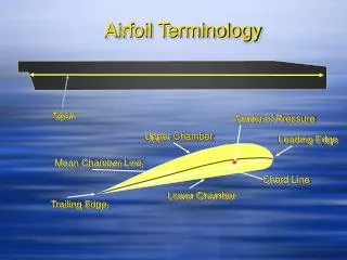
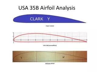
Aspects of Supercritical airfoils • Low shock drag losses at Transonic speed • Shock stands at a significantly aft location • Upper surface has a pressure plateau • Extremely steep pressure recovery towards the aft of upper surface • Lower surface has roughly constant negative pressure coefficient
Analysis Method 1:Full potential Equation Brief overview: • Construct a smooth grid with adequate resolution near the airfoil surface • Initialize φ to 0.0 and compute metrics at all reqd. points • Discretize the FPE equation into a sparse matrix form using finite difference formulation • Solve for φ at the next time step using any of the efficient solution techniques • Compute Γ and φ at boundaries and far-field • Compute loads and Cp using φ
FPE (Contd.) • O-grid used because it accurately follows rounded bodies without much skewness • Conformal mapping methods are used • O-grid is better suited for subsonic flows: Outer boundary tends to match the region of influence of solid body
Euler/N-S formulation • System of Equations • Roe’s flux difference splitting used for Inviscid fluxes • Central differencing used for Viscous fluxes • No-slip boundary condition at wall imposed • Free-stream boundary conditions at outer boundaries • Riemann invariants proved to be causing a limit cycle behavior and so were not used for viscous cases • 2-step Explicit time integration scheme used
Euler/N-S (Contd.) • C-grid provides good clustering control for viscous problems • Elliptic PDEs used to generate a grid over the airfoil
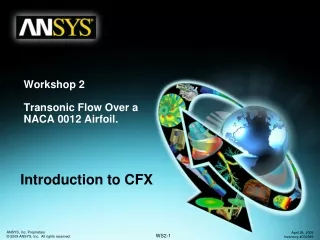
Validation of Analysis method (FPE) NACA 0012, M=0.63, Alpha = 2.0 NACA0012, M=0.72, Alpha = 0.0
Validation (Euler/N-S) NACA 0012, M=0.63, Alpha = 2.0 Log Residual plot
Validation (Euler/N-S) NACA 0012, M=0.72, Alpha = 0.0 Log Residual plot
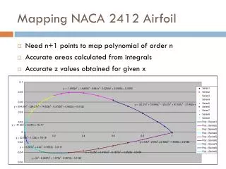
Design Methodology • Navier-Stokes solver: slow and time consuming • Sometimes limit cycle behavior observed and flux limiter had to used for convergence • Numerical optimization method used with FPE analysis method • Airfoil surface approximated as a polynomial • Squared difference of Cp calculated and Target Cp is used as objective function for minimization • Care taken to close the airfoil trailing edge and leading edge • Some intermediate airfoil shapes and Cp distributions were also observed
Results Cp distribution and Airfoil shape after a few iterations
Results In this figure, the Angle of attack was fixed at 0.0
Conclusions and Future Work • Analysis tool and its capabilities have been explored • The design method has been tested for new airfoil generation • Have to generate a target Cp distribution for a supercritical airfoil to design • Involves understanding the performance requirements of the airfoil • Extend to 3-D wings if time and computational effort permits