Download
1 / 1
10 likes | 168 Views
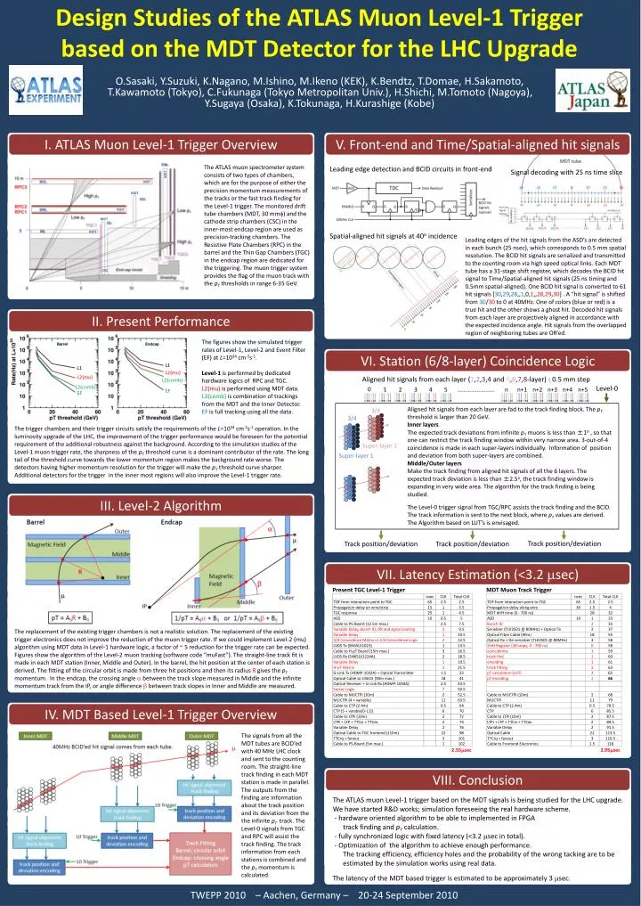
I . ATLAS Muon Level-1 Trigger Overview. V. Front-end and Time/Spatial-aligned hit signals.

E N D
I. ATLAS Muon Level-1 Trigger Overview V. Front-end and Time/Spatial-aligned hit signals The ATLAS muon spectrometer system consists of two types of chambers, which are for the purpose of either the precision momentum measurements of the tracks or the fast track finding for the Level-1 trigger. The monitored drift tube chambers (MDT, 30 mmf) and the cathode strip chambers (CSC) in the inner-most endcap region are used as precision-tracking chambers. The Resistive Plate Chambers (RPC) in the barrel and the Thin Gap Chambers (TGC) in the endcap region are dedicated for the triggering. The muon trigger system provides the flag of the muon track with the pT thresholds in range 6-35 GeV. Leading edge detection and BCID circuits in front-end Signal decoding with 25 ns time slice MDT MDT MDT MDT MDT MDT Spatial-aligned hit signals at 40o incidence Leading edges of the hit signals from the ASD’s are detected in each bunch (25 nsec), which corresponds to 0.5 mm spatial resolution. The BCID hit signals are serialized and transmitted to the counting room via high speed optical links. Each MDT tube has a 31-stage shift register, which decodes the BCID hit signal to Time/Spatial-aligned hit signals (25 ns timing and 0.5mm spatial-aligned). One BCID hit signal is converted to 61 hit signals [30,29,28,,1,0,1,,28,29,30] . A “hit signal” is shifted from 30/30 to 0 at 40MHz. One of colors (blue or red) is a true hit and the other shows a ghost hit. Decoded hit signals from each layer are projectively aligned in accordance with the expected incidence angle. Hit signals from the overlapped region of neighboring tubes are OR’ed. CSC Design Studies of the ATLAS Muon Level-1 Trigger based on the MDT Detector for the LHC Upgrade II. Present Performance The figures show the simulated trigger rates of Level-1, Level-2 and Event Filter (EF) at L=1034 cm-2s-1. Level-1 is performed by dedicated hardware logics of RPC and TGC. L2(mu) is performed using MDT data. L3(comb) is combination of trackings from the MDT and the Inner Detector. EF is full tracking using all the data. VI. Station (6/8-layer) Coincidence Logic L1 L1 L2(mu) L2(mu) Aligned hit signals from each layer (1,2,3,4 and 5,6,7,8-layer) : 0.5 mm step L2(comb) L2(comb) Level-0 0 1 2 3 4 ……………………. n+1 n+2 n+3 n+4 n+5 5 n EF EF Aligned hit signals from each layer are fad to the track finding block. The pT threshold is larger than 20 GeV. Inner layers The expected track deviations from infinite pT muons is less than ±1o , so that one can restrict the track finding window within very narrow area. 3-out-of-4 coincidence is made in each super-layers individually. Information of position and deviation from both super-layers are combined. Middle/Outer layers Make the track finding from aligned hit signals of all the 6 layers. The expected track deviation is less than ±2.5o, the track finding window is expanding in very wide area. The algorithm for the track finding is being studied. The Level-0 trigger signal from TGC/RPC assists the track finding and the BCID. The track information is sent to the next block, where pT values are derived. The Algorithm based on LUT’s is envisaged. 3/4 3/4 The trigger chambers and their trigger circuits satisfy the requirements of the L=1034 cm-2s-1 operation. In the luminosity upgrade of the LHC, the improvement of the trigger performance would be foreseen for the potential requirement of the additional robustness against the background. According to the simulation studies of the Level-1 muon trigger rate, the sharpness of the pT threshold curve is a dominant contributor of the rate. The long tail of the threshold curve towards the lower momentum region makes the background rate worse. The detectors having higher momentum resolution for the trigger will make the pT threshold curve sharper. Additional detectors for the trigger in the inner most regions will also improve the Level-1 trigger rate. Super-layer 1 Super-layer 1 III. Level-2 Algorithm O.Sasaki, Y.Suzuki, K.Nagano, M.Ishino, M.Ikeno (KEK), K.Bendtz, T.Domae, H.Sakamoto, T.Kawamoto(Tokyo), C.Fukunaga (Tokyo Metropolitan Univ.), H.Shichi, M.Tomoto(Nagoya), Y.Sugaya (Osaka), K.Tokunaga, H.Kurashige (Kobe) Track position/deviation Track position/deviation Track position/deviation VII. Latency Estimation (<3.2 msec) The replacement of the existing trigger chambers is not a realistic solution. The replacement of the existing trigger electronics does not improve the reduction of the muon trigger rate. If we could implement Level-2 (mu) algorithm using MDT data in Level-1 hardware logic, a factor of ~ 5 reduction for the trigger rate can be expected. Figures show the algorithm of the Level-2 muon tracking (software code “muFast”). The straight-line track fit is made in each MDT station (Inner, Middle and Outer). In the barrel, the hit position at the center of each station is derived. The fitting of the circular orbit is made from three hit positions and then its radius R gives the pT momentum. In the endcap, the crossing angle a between the track slope measured in Middle and the infinite momentum track from the IP, or angle difference b between track slopes in Inner and Middle are measured. IV. MDT Based Level-1 Trigger Overview The signals from all the MDT tubes are BCID’ed with 40 MHz LHC clock and sent to the counting room. The straight-line track finding in each MDT station is made in parallel. The outputs from the finding are information about the track position and its deviation from the the infinite pT track. The Level-0 signals from TGC and RPC will assist the track finding. The track information from each stations is combined and the pT momentum is calculated. VIII. Conclusion The ATLAS muon Level-1 trigger based on the MDT signals is being studied for the LHC upgrade. We have started R&D works; simulation foreseeing the real hardware scheme. - hardware oriented algorithm to be able to implemented in FPGA track finding and pT calculation. - fully synchronized logic with fixed latency (<3.2 msec in total). - Optimization of the algorithm to achieve enough performance. The tracking efficiency, efficiency holes and the probability of the wrong tacking are to be estimated by the simulation works using real data. The latency of the MDT based trigger is estimated to be approximately 3 msec. TWEPP 2010 – Aachen, Germany – 20-24 September 2010