Download
1 / 8
80 likes | 86 Views
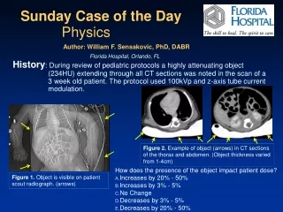
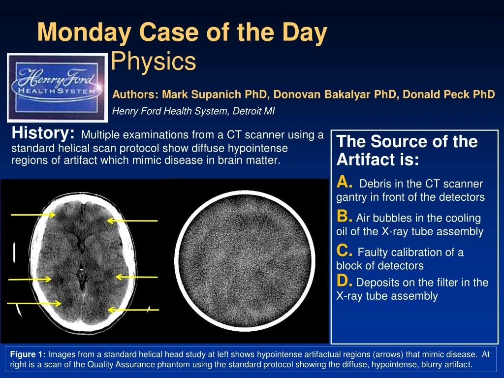
History: Multiple examinations from a CT scanner using a standard helical scan protocol show diffuse hypointense regions of artifact which mimic disease in brain matter. Monday Case of the Day. Physics. Authors: Mark Supanich PhD, Donovan Bakalyar PhD, Donald Peck PhD.

E N D
History:Multiple examinations from a CT scanner using a standard helical scan protocol show diffuse hypointense regions of artifact which mimic disease in brain matter. Monday Case of the Day Physics Authors: Mark Supanich PhD, Donovan Bakalyar PhD, Donald Peck PhD Henry Ford Health System, Detroit MI The Source of the Artifact is: A. Debris in the CT scanner gantry in front of the detectors B. Air bubbles in the cooling oil of the X-ray tube assembly C.Faulty calibration of a block of detectorsD. Deposits on the filter in the X-ray tube assembly Figure 1: Images from a standard helical head study at left shows hypointense artifactual regions (arrows) that mimic disease. At right is a scan of the Quality Assurance phantom using the standard protocol showing the diffuse, hypointense, blurry artifact.
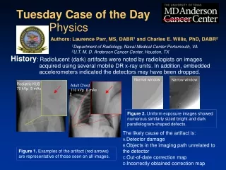
Findings: A Physicist was able to reproduce the diffuse, blurry artifact when scanning a Quality Assurance (QA) phantom using the standard head protocols (Figure 2). The artifact was also observed in previous tech QA scans after windowing and leveling. No foreign objects or stains were noted on the gantry or on the patient bed. Hypointense regions were noted not to be entirely contiguous from slice to slice (Figure 2). Figure 2: Adjacent slices of QA phantom showing diffuse hypointense regions that differ in appearance in each slice.
Diagnosis:B.Air bubbles in the cooling oil of the X-ray tube assembly
Discussion:As photons exit the tube assembly, they pass through cooling oil. If the photons pass through air bubbles located in the cooling oil, they are less likely to be attenuated than if they passed only through oil. The decreased attenuation in each CT view leads to a reconstructed pattern of hypointense regions. Figure 3: Diagram from reference 1 showing that photons pass through cooling oil as they exit the x-ray tube housing.
Discussion:Small air bubbles in the cooling oil are hypoattenuating and are geometrically magnified in an attenuation profile as shown in Figure 4. Air bubbles move through the liquid as the gantry and the tube assembly rotate, resulting in different attenuation profiles at each view. (Stationary bubbles would result in thick, fuzzy circles.) This view-to-view movement results in the non-circular appearance of the blotchy patterns which, in turn, masks the behavior normally expected from CT artifacts. Figure 4. Cutaway magnified view of anode with air bubbles in surrounding oil shown at top. The photons exit the tube assembly and encounter an attenuating object. The combination of the hypoattenuating air bubbles and the object result in an attenuation profile with a decrease in attenuation at certain projections due to air bubbles.
Discussion:The vendor’s service engineer was contacted to perform maintenance on the tube to remove the air bubbles. Figure 5 shows the QC phantom imaged with the air bubbles present (left) and after servicing of the tube (right). Figure 5: Quality Assurance phantom imaged and displayed at the same WW/WL with air bubbles present in cooling oil (left) and with no bubbles present (right).
Discussion: Choice A: Debris in front of detector would result in artifacts in the images that would be smaller and sharper than observed due to minimal geometric magnification. Choice C: Faulty calibration of a block of detectors could explain the existence of one circular hypointense region at isocenter as shown in Figure 6 from reference 2, but the multiple areas of hypointensity and their non-circular shape rule out this answer. Choice D: Deposits on the filter in the assembly would show the effects of geometric blurring, but would lead to regions of hyperintensity due to the increased attenuation of the photons encountering the deposits. The resulting artifacts would be circular, as the location of the attenuation change would be fixed in the detector frame of reference. Figure 6: Regions of hypointensity due to the faulty calibration of a block of detectors due to a foreign substance on the collimator assembly.. The location of the artifact varies from scan to scan due to patient positioning. Adapted from reference 2.
References/Bibliography: • Schardt et al. “New x-ray tube performance in computed tomography by introducing the rotating envelope tube technology,” Med Phys 2004; 31(9): 2699-2076. • Cody, D. et al. “Multi-detector row CT artifacts that mimic disease,” Radiology 2005;236:756-761