Download
1 / 11
110 likes | 193 Views
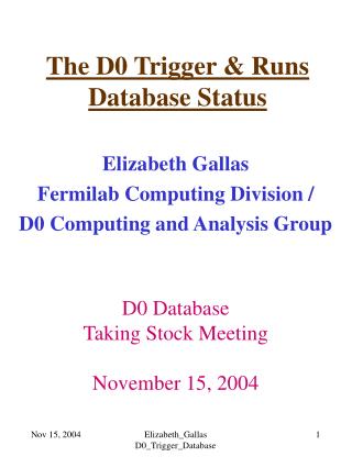
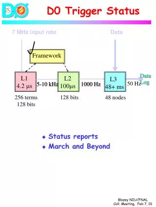
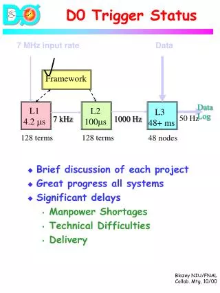
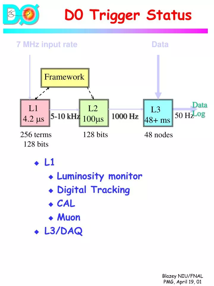
D0 Trigger Status. 7 MHz input rate Data. Framework. Data Log. L1 4.2 m s. L2 100 m s. L3 48+ ms. 50 Hz. 5-10 kHz. 1000 Hz. 48 nodes. 256 terms 128 bits. 128 bits. L1 Luminosity monitor Digital Tracking CAL Muon L3/DAQ. Luminosity Monitor.

E N D
D0 Trigger Status 7 MHz input rate Data Framework Data Log L1 4.2 ms L2 100ms L3 48+ms 50 Hz 5-10 kHz 1000 Hz 48 nodes 256 terms 128 bits 128 bits • L1 • Luminosity monitor • Digital Tracking • CAL • Muon • L3/DAQ
Luminosity Monitor • Detector/readout installed • Timed-in • Providing minbias triggers using Run I electronics. • Final Electronics • TDC in production • Vertex boards 1-Jun • Expect multiple interaction triggers, luminosity database to be completed by the end of the year, delayed because lead-postdoc departed.
CTT Organization showing links to the L1 TM, L2 PreProcessors and L3 AFE MIX DB/DBTC COL BC TM L3 OCT 1 CFT L1CFT Ax. /CPS Ax. L3 75 L3 OCT 2 L3 OCT 3 L2CFT · Q 1 L3 L2PS OCT 4 L2CFT · Q 2 L3 L2PS OCT 5 L2CFT Q 3 · 40 L3 L2PS OCT 6 L2CFT · Q 4 L3 · L2PS OCT 7 CPS · L3 Ax. · m OCT 8 L1 TM 5 OLR 1 L2STT SEXT 1 L3 OLR 2 L2STT SEXT 2 L3 OLR 3 L2STT SEXT 3 L3 OLR 4 L2STT SEXT 4 L3 OLR 5 L2STT SEXT 5 L3 CFT OLR 6 Stereo. L2STT SEXT 6 75 L3 L2PS N U L3 5 L2PS N V L3 CPS L2PS Stereo S U L3 10 L2PS S V L3 L2FPS N U L3 L2FPS N V L3 FPS L1FPS 16 L3 L2FPS 32 S U L3 L2FPS S V L3 LEGEND Analog Boards FSC LINK LVDS LINK the inset shows CFT LVDS LINK the number of G LINK Stereo. each type 3 TRANSITION CARDS DAUGHTER CARDS Each color Each filling corresponds to a corresponds to a Created by Manuel I. Martin different flavor different flavor May. 6, 99 L1CTP/FPS/FPD
L1 CTP/FPS/FPD Digital Status • Mixer(Fermilab-CD) • Effort is delayed, shorthanded, discussing options with CD/D0-Electronics group. • 30-May: A half super-sector (2 of 20 boards.) • 25-July: Full system (estimate <1 week access) • Broadcasters/Collectors(Fermi-D0) • 65% of hardware, 70% of firmware. • 100% crates/PS/Cables • Currently installing single cards to test software & download • May shutdown, hit occupancy trigger • 11-June complete hardware installation (estimate 2-4 wks access) • 1-Aug full system integration • Difficult keeping the schedule, short a tech and programmer to help lead engineer.
L1 CAL Component Status • Components • All in or nearing production expect full complement mid-June • Summers/Drivers at vendor • Receivers at Si-Det • Currently • CC populated • Timed in • Single cal tower trigger in days • Next • Readout to L2 & L3 • Quadrant capability • Completion of system • 1-2 weeks access • Reliable clock system. Has been difficult and some concern expert (Xiaonan Li) will be leaving soon.
L1 MUON Status • Components • all in production, should be available for accesses. • Full set trigger system by July 1 • Centroid finders Aug 1. • Currently • A few central octants • Triggering on beam • After two week shutdown • Full central region • 1 octant in each end region • Completion of system will require • Additional 2 weeks installation access • Additional 2 weeks commissioning access
Digitizing Crates (2 of 16 groups) Data pathway o o o Receiver Collector (1 of 8) o o o VBDs Fiber Path (8 total) Event Tag Generator Levels 1,2 Trigger data o o o o o o Event tag path o o o o o o Segment Bridge Processor Nodes (4 groups of 16) DAQ/L3 Originally a single multipurpose card (~300) used in most components with firmware specific to application.
Moving Counting House Fixed Counting House V B D i SIB3 FCI fiber copper DCI L3I VRC (PC) copper VBDs ETI L3 filter node PCs L1 SB (PCs) V B D i’ Multiple 100 MB/s INOVA links SIB3 fiber copper ETG (PC) L3 Design In January abandoned this approach in favor of more, less complicated individual components. • VRC = VBDI + SIB3 • SB = 12 SIB2 • Node = Motherboard + 4 SIB2 • ETG = VBDI’ + SIB3
L3 Status/Schedule • Currently VRC, SB, ETG emulated w/ capability of several Hz. • Assembling an intermediate 100-200 Hz system to support commissioning. Expected mid-May • Basically VRC emulation replaced w/ hardware VBDI and SIB1. • SIB1 exists and integrated • VBDI in assembly • Design work on VBDI’, SIB2 and SIB3 proceeding. • SIB2 June 1 • SIB3 July 1 • Full 1 kHz 1-Aug
L3/DAQ Management • Since January have had weekly L3 Review or oversight meetings. Successful in promoting recent progress. • Today first meeting of L3 Planning Group charged with • developing a schedule for completion of hardware and software by Sept 1 • suggesting alternatives • identifying resources. • Major issues • Hardware delivery • Supportability of NT filtering. • Possibilities include • Present course • Separate DAQ & filtering farms • Hope for recommendation in one month and may request resources at that time.
Summary • L1 Luminosity • Operational • >June • Completion depends on identifying manpower • Little or no access. • L1 Tracking • First steps • August • need technical assistance • 4+ weeks access. • L1 Calorimeter • CC operational • June • Help with Clock • <2 weeks access. • L1 Muon • Central operational • July • 4 week access. • L3 • Supporting Commissioning • September • Evaluating Options • No access