Download
1 / 11
110 likes | 234 Views
ALICE Trigger Status. A. Jusko for Birmingham group. DCS workshop, 10/10/2006. Content. Status Integration with ECS and DAQ Interface to DCS. Final CTP setup. CTP LTU (LVDS). BC clock (coax. Cable). LTU - FE (LVDS). RoI connections. Status. 2 setups installed in Birmingham

E N D
ALICE Trigger Status A. Jusko for Birmingham group DCS workshop, 10/10/2006 DCS workshop, 10/10/06
Content • Status • Integration with ECS and DAQ • Interface to DCS ALICE Trigger Status
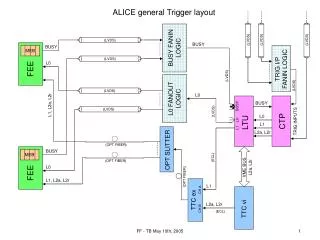
Final CTP setup CTP LTU (LVDS) BC clock (coax. Cable) LTU - FE (LVDS) RoI connections ALICE Trigger Status
Status • 2 setups installed in Birmingham • 2 setups installed in CERN lab, 1 is connected to DAQ/ECS reference setup • Set of boards for 5th setup available • Software for CTP configuration/testing ready • CTP proxy code for integration with ECS ready • CTP DIM server is being developed, ‘CTP counters monitoring’ part ready ALICE Trigger Status
CTP-ECS-DAQ integration • - Started in July 2006 • - CTP installed in Birmingham lab at CERN • and connected to DAQ lab (60 m) • DAQ emulates two detectors (DDG) • DAQ receives CTP Readout and Interaction Record via DDL • Front-end Emulator (DDG) receives via TTC L0/L1 triggers and L1 /L2 messages, generates the event data and generates BUSY signals • Under ECS control CTP provides correct Start and End of the run sequences (SOD,EOD) • ECS/CTP/DAQ are tested to configure and run any partition out of two detectors ALICE Trigger Status
CTP – DCS interface • All voltages are read out through I2C link which can be connected to: • CTP INT board VME bus CTP DIM server • PC equipped with I2C interface DIM server –tested on each board with I2C-parallel port adapter connected to PC with Windows/XP ALICE Trigger Status
DCS usage - DCS network - monitoring - control • DCS network connects together 12 computers : • linux boot/disk server • 8 diskless VME computers controlling 8 VME crates • PVSS project node • Operator node ALICE Trigger Status
Monitoring • ~ 1000 integer values, ~per several minutes, • accesible through DIM servers running • on CTP VME computers • counters: 727 + 24*12 = 1015 • voltages: (11+24)*4 = 140 • temperatures: 11+24 =35 More levels of warnings and alarm required in case the values go out of given range ALICE Trigger Status
Control • automatic powering off the crate in case of high temperature, subject to actions associated with alarms • remote SYSRESET VME signal for each crate – has it been tested already ? ALICE Trigger Status
Summary • CTP hardware ready for installation in the pit • Integration with DAQ/ECS going well • Still to be done: • boot/disk server configuration • the usage of ECS/DAQ database • GUI for preparing partition configurations • DIM servers accessing CTP services • PVSS project ALICE Trigger Status