Download
1 / 27
270 likes | 277 Views
Xin Gao and Luca Macchiarulo Tuesday January 17 th ,2012, University of Hawaii Belle II TRG/DAQ Workshop. TOP Trigger Status. Schedule. Overall TOP trigger structure Front-End Triggering (FET) Algorithm Design Implementation Test Combining Board Proposal for implementation

E N D
Xin Gao and Luca Macchiarulo Tuesday January 17th,2012, University of Hawaii Belle II TRG/DAQ Workshop TOP Trigger Status
Schedule • Overall TOP trigger structure • Front-End Triggering (FET) • Algorithm • Design • Implementation • Test • Combining Board • Proposal for implementation • Global TOP trigger – back-end trigger (BET) • Proposal for implementation • Conclusions
FET Algorithm 90° 40° 120° e- e+ • Estimation of the interaction point and time based on the received photon pattern is not straightforward: • A small separation between the horizontal borders of the counters folds the Cherenkov cone into degenerate patterns. • The estimation must be done in a couple of μs. • Taking advantage of the information contained in the PDF (probability density function) of the time and space data. Compare with the candidate PDFs. Find out the PDF that best matches the received time patterns. Time information from the photon detector Report event time and position.
FET Firmware Design • Note: the firmware was originally designed for the original specs requiring 8 fiber optic links dedicated per each sector • The most recent implementation uses only 4 links for the trigger information at an higher data rate • Consequence on existing design • Reduce the sorting network to a 4-input design • Is 2x data rate sustainable? • Probably ok for original trigger – only timing • Trickier for more info – see below
Firmware Design – new 4-fiber input ? Enough BW ?
Implementation and Test Results • Implementation: • Virtex 4 FPGA (XC4VFX40-10FFG672I). • Timing constraint met • Resource usage (LUT limited) • Slice: 14255 (67%) • RAMB16s: 110 (76%) • Verification • Simulation (5000 MC test vectors): identical to C model • Code Coverage (added test vectors to cover VHDL constructs) • Test on Board (at speed including Aurora interfaces)
Note on “verification” • From the point of view of the design/algorithm, the FET is completely verified with an at-speed board-level simulation. • So, we should not have surprises with the implementation (save possibly for radiation-related SEUs) • However, this assumes that the PDFs used are a sufficiently close representation of the events • Depends on # and accuracy of GEANT simulations • Ideally, real beamtest data should be used to refine • We can try to incorporate the data taken at Fermilab • Good property of the design: flexibility - “correct” PDFs can be easily changed almost on-the fly (requires reprogramming the device).
Combiner Boards • Need to merge the information of 8 Front End Trigger Boards • No further elaboration of the signal • Only if necessary some data compression • Relatively simple operation: can use an identical sorting network as FET (with 8 inputs): • Each FET output is a serial input with triggering and timing information • Add the tag of origin, order the timing information and retransmit to higher level
Combiner Board To BET 8-way Sorter From 8 FETs
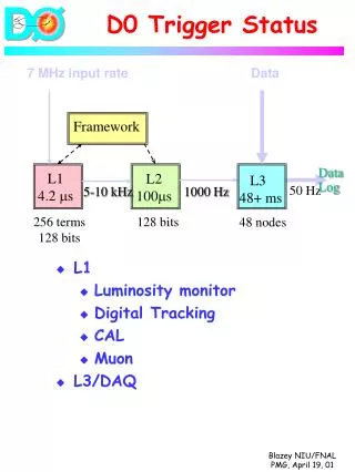
Back-End Trigger (BET) • The final trigger again combines (timing) information from all the staves • Can potentially achieve better timing resolution by combining different estimates for event time • Possible algorithms (in order of complexity): • Simplest: pass every L1 trigger received, with masking • Average estimate in a given window • Use of confidence value generated by PDFs to weigh estimates • Use of geometrical information - estimates of hit positions
BET- every trigger • To avoid flooding the Global Trigger with TOP triggers belonging to the same event: • After a FET trigger arrives, transmit it to global trigger • Mask off all subsequent triggers within a given timestamp • VERY easy to implement • Loses information from other hits • First hit estimate not necessarily more reliable
BET – hit combination strategies • Every BET option that combines hit needs to decide when hits belong to the same event • Whenever a trigger from FET occurs, starts a counter to see if other single stave trigger occurs in a given maximum time (critical – do not want to add too much latency) • Estimate a best time based on hits (see below for options) • At the end of the window, output the estimated time
BET – time average estimate If more than 1 trigger occurs, compute the time as the arithmetic average of the times • (t1+t2)/2, (t1+t2+t3)/3, (t1+t2+t3+t4)/4... • Hard part – division by 3,5,7,11,13: implement all separate divisions as fixed number multiplications • All triggers in the window (from different staves) are used in the estimate • Reliable and less reliable estimates are not distinguished • No change in FET – minimum overhead
BET – weighted time average • If more than 1 trigger occurs, compute the time as • (w1*t1+w2*t2)/(w1+w2), (w1*t1+w2*t2+w3*t3)/(w1+w2+w3), ... • In this case a real division is necessary – slight cost in latency • Weights (confidence levels) are the maximum value from PDF estimation - already calculated in FET! • Requires extra output (confidence level) from FET
BET – Geometric information • If other triggers occur, use the estimated hit positions on the stave and asses the probability for the given configuration on the basis of expected events • Problem with unexpected event suppression? • Calculation of hit position implicitly calculated in FET already • Requires other extra outputs (confidence level + hit position) from FET • More precise if stave further divided – some issues with FET FPGA size.
Conclusions • Status of TOP trigger • Structure: 16 FETs → 2 Combiners → 1 BET • FETs: • designed and verified • changes required for input fiber reductions • Minimal (easy) changes for BET improvement • Combiners: • Main components (Aurora, sorter) designed and verified • Assembly needed • BETs: • Some components (AURORA cores, sorter, PDF checker) designed • Algorithm and complete design required
FET Algorithm (cont.) Use both Time and Space information Time quantization: 1ns Background noise: 10 MHz Use both Time and Space information Time quantization: 2ns Background noise: 10 MHz Only Time information is used Time quantization: 1ns Background noise: 40 MHz Only Time information is used Time quantization: 1ns Background noise: 10 MHz
Firmware Design (cont.) • Trigger Logic Correlate with 200 LUTs MAX event time and position Sorted timing info • LUTs: 200 x 64 x 20 bits • To save resource usage, only 100 correlators are used to perform the 200 correlation operations. • The frequency of the trigger block is twice the frequency of the sorter to avoid throughput bottleneck
Implementation Results • Virtex 4 FPGA (XC4VFX40-10FFG672I). • Resource usage • Slice: 14255 (67%). • Slice FFs: 21112 (56%). • 4 input LUTs: 16923 (45%). • RAMB16s: 110 (76%). All timing constraints were met!
Verification based on Simulation • Self Checking Testbench Firmware Source Code 5000 Test Patterns From Monte-Carlo Simulation Check if match Software Simulator • Result • Perfect Match! • The firmware has realized the design intention.
Code Coverage • Check if all the code has been exercised in the test. • Include statement coverage, branch coverage, condition coverage, FSM coverage, etc. • Compile and simulate the design in modelsim. • Report is generated for each design file. • For the stimulus generated by Monte-Carlo simulation • Generally, 75~100%. • Some corner cases are not covered, e.g., fifo full condition. • Some fake stimulus are generated to achieve 100% coverage for statements, branches, conditions and FSMs.
Test on Board Load the test patterns into the FPGA through the USB interface. Start Test. Read trigger data out from the USB interface. Compare the obtained results to those from the software simulator Firmware under test Optical cables PC Control & status regs USB Control FIFO FIFO USB FIFO FIFO The firmware works as expected! Aurora Interfaces
Test Results • Verification based on Simulation • Code Coverage • Test on Board