Download
1 / 25
250 likes | 369 Views
Power distribution in SLHC trackers using embedded DC-DC converters. F.Faccio, G.Blanchot, S.Michelis, C.Fuentes, B.Allongue, S.Orlandi CERN – PH-ESE. Outline. Proposed scheme using DC-DC converters Specific technical difficulties Semiconductor technology EMC (conducted and radiated noise)

E N D
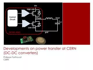
Power distribution in SLHC trackers using embedded DC-DC converters F.Faccio, G.Blanchot, S.Michelis, C.Fuentes, B.Allongue, S.Orlandi CERN – PH-ESE
Outline Proposed scheme using DC-DC converters Specific technical difficulties Semiconductor technology EMC (conducted and radiated noise) Inductor design ASIC development and integration aspects Conclusion F.Faccio, PH/ESE
SLHC-specific requirements • Converters to be placed inside the tracker volume Magnetic field (up to 4T) Radiation field (>100Mrd, >1015n/cm2) Environment sensitive to noise (EMI) • No commercial component exists, need for a custom development F.Faccio, PH/ESE
Proposed distribution scheme (ATLAS Short Strip concept) Rod/stave 10-12V 2 Converter stage2 on-chip Detector Hybrid controller 2.5V bus 1.8V bus 10-12V 2 Converter stage 1 Voltage for SMC and optoelectronics generated locally by a converter stage 1 Distribution with 2 conversion stages • Only 1 line to the stave (10-12V), all other voltages generated locally • Stage 1: • It is composed of 2 converters • It generates 2 intermediate power buses (2.5 for analog and 1.8 for digital) • It provides 1.6W for analog and 2W for digital, but could provide more than 2x that power – allowing to power 4 hybrids with even higher efficiency if mechanical integration allows it • Stage 2: • Switched capacitor converter with fixed conversion ratio = 2 • It is integrated directly on-chip (2 per chip, analog and digital) • Efficient because able to provide locally the voltage required by the load (different for analog and digital) F.Faccio, PH/ESE
2.5V power bus 1.8V power bus Serial “chip enable” bus from HC DC-DC HC Serial “module enable” bus from SMC 10-12V Offered modularity Easy control • Module power turned on/off by SMC via serial bus to DC-DC converters in stage 1 • FE ASIC individually turned on/off by HC via serial bus • Other configurations possible, for instance: • HC powered via separate 2.5V line under the control of SMC • DC-DC converters on module controlled by HC) Individual converter composition • DC-DC ASIC in plastic package (~7x7x1 mm) • A few SMD components • Air-core inductor • Size dependent on chosen design (to be discussed later) F.Faccio, PH/ESE
Outline Proposed scheme using DC-DC converters Specific technical difficulties Semiconductor technology EMC (conducted and radiated noise) Inductor design ASIC development and integration aspects Conclusion F.Faccio, PH/ESE
Semiconductor technology • The converter requires the use of a technology able to work up to at least 15-20V • Such technology is very different from the advanced low-voltage (1-2.5V) CMOS processes used for readout and control electronics, for which we know well the radiation performance and how to improve it • High-voltage technologies are typically tailored for automotive applications • Need to survey the market and develop radiation-tolerant design techniques enabling the converter to survive the SLHC radiation environment (> 10Mrd) • A 0.35mm technology has been extensively tested (see next slide) • In the near future, 3 other technologies will be tested in the 0.18-0.13mm nodes • Properties of high-voltage transistors largely determine converter’s performance • Need for small Ron, and small gate capacitance (especially Cgd) for given Ron! Prototypes in 0.35mm F.Faccio, PH/ESE
Candidate technologies • All technologies offer “low voltage” devices from a mixed-signal technology, with the addition of a “high-voltage” module (up to 80V in some cases) • Some properties of the high-voltage transistors are summarized in the table below (for NMOS transistors, that have to be used as switches) F.Faccio, PH/ESE
Examples of TID effects (NMOS) Leakage (large increase) Large Vth shift No leakage, small Vth shift F.Faccio, PH/ESE
Examples of displacement damage effects Effect visible in output characteristics [Id=f(Vds)] … and in on-resistance (Ron) F.Faccio, PH/ESE
Summary of results • One technology (0.25mm node) has demonstrated radiation tolerance compatible with benchmark: • NMOS Ron decrease below 60% for 2.5∙1015 n/cm2 (1MeV equivalent) • Vth shift manageable (below 200mV for NMOS, 400mV for PMOS @ 350Mrd) • Negligible leakage current with TID • Overall, radiation could affect converter performance as small drop of efficiency (below 5%) • One technology (0.13mm node) could satisfy requirements for installation further from collision point, where fluence is limited below 1∙1015 n/cm2 (1MeV equivalent) • The other 2 technologies are less performant and will not be considered further • Conclusion: • While starting prototype work in the 0.25um technology, another 0.18mm technology will be tested in 2009 (we look for a second source with comparable radiation performance) F.Faccio, PH/ESE
EMC issues Without any doubt, switching converters inside the tracker are an additional source of noise Noise can be conducted (via the cables) or radiated (near-field emission from inductor, loops, and switching nodes). Both propagation paths have to be controlled Action is required in 2 directions Decrease the noise from the source Control the noise path – ultimately design a more robust system EMI (dψ/dt) EMI (dV/dt) EMI (dI/dt) EMI (dI/dt) F.Faccio, PH/ESE
Conducted CM noise from custom prototypes • Several custom DC-DC prototypes (buck topology) using discrete commercial components have been manufactured • Proper design of PCB and choice of passive components (caps) drastically decrease the conducted noise “Reference” level based on Class A limit from CISPR11 converted to current on a given impedance (Careful: this is NOT a real limit) Noise (dBuA) Frequency (Hz) Frequency (Hz) Example: output common mode noise for 2 custom prototypes using identical discrete components (commercial driver + switches). Only the design of the PCB and the passive components differ F.Faccio, PH/ESE
Radiated noise (magnetic field) The susceptibility of systems to the magnetic field emitted by inductors of power converters is a major concern. System tests were carried out on TOTEM, with a coil driven by an amplified RF source. The coil is accurately positioned above the detector, the bondings and the ASICs and the induced noise is analyzed from the test DAQ. 538 nH air core, 1A. Noise decreases when the inductance is placed at some distance from the detector F.Faccio, PH/ESE
Susceptibility to Magnetic FieldShielding of inductor (Al wrap) The shielding of the coil with Al foil allows protecting the front-end against radiated noise F.Faccio, PH/ESE
Powering a Si Strip module with DC-DC converter prototypes The front-end ASICs were powered by a DC/DC converter prototype (PH-ESE) – switching frequency = 1MHz • Measurements on the TOTEM Si Strip module, with detector biased • 3 locations were exercised, with no impact on the noise performance of the system • Cables were still relatively long in this test • When powered with very short cables, marginal noise increase for only 1 prototype (no noise increase for another) • DCDC mounted on top of the detector without shield, d < 15 mm to be able to see some coupling effect • This is radiated noise (cables as in previous measurements, hence no influence of conducted noise as before) • Main radiated field from inductor. We need toshield the inductor F.Faccio, PH/ESE
Requirements for the inductor • Value: up to 500-700nH (this is feasible with air-core) • Compact for high integration • Light for low material budget • With small ESR both in DC and AC (at the switching frequency) for high efficiency • It needs to be shielded for low radiated noise F.Faccio, PH/ESE
Different air-core inductors • Air-core inductors can be manufactured in different configurations: planar, solenoid, toroid Planar (on PCB) Solenoid Toroid ESR(DC)>100mW ESR(DC)~10-30mW ESR(DC)~20-30mW for custom winding, largely dependent on implementation for PCB toroid F.Faccio, PH/ESE
“Optimized” PCB toroid (1) • Custom design exploiting PCB technology: easy to manufacture, characteristics well reproducible • Design can be optimized for low volume, low ESR, minimum radiated noise • With the help of simulation tools (Ansoft Maxwell 3D and Q3D Extractor), we estimated inductance, capacitance and ESR for different designs. This guided the choice of the samples to manufacture as prototypes • The addition of two Al layers (top, bottom) shields the parasitic radiated field efficiently • A series of PCB toroids has been designed and is now being manufactured • Measurements will be compared to simulation F.Faccio, PH/ESE
Outline Proposed scheme using DC-DC converters Specific technical difficulties Semiconductor technology EMC (conducted and radiated noise) Inductor design ASIC development and integration aspects Conclusion F.Faccio, PH/ESE
ASIC development – 1st generation • ASIC designer: Stefano Michelis • Prototype for “conversion stage 1” • First prototype designed and manufactured in AMIS I3T80 technology • Simple buck topology • Vin up to 10V • Vout=2.5V • Iout up to 1.5A • switching frequency 0.3-1.2 MHz • ASIC included main functions only (switches, control circuitry) • External compensation network, reference voltage and sawtooth generator required • Functionality tested OK • Prototype used already to power detector modules F.Faccio, PH/ESE
ASIC development – 2nd generation • Second generation prototype • Still manufactured in AMIS 0.35mm • Features: • VIN and Power Rail Operation from +3.3V to +12V • Selectable output voltage (nominal 2.5V) • Maximum output current: 3A • Fast Transient Response - 0 to 100% Duty Cycle • 14MHz Bandwidth Error Amplifier with 10V/μs Slew Rate • Internal oscillator fixed at 1Mhz, programmable from 400kHz to 3MHz with external resistor • Internal voltage reference (nominally (1.2V) • Remote Voltage Sensing with Unity Gain • Programmable delay between gate signals • Integrated feedback loop with bandwidth of 20Khz • Submitted December 08, expected back in April 09 • Mounted in 7x7mm QFN package F.Faccio, PH/ESE
Inductor SMD devices ASIC PCB substrate 2 converters (analog and digital power) Integration in ATLAS SCT module design From D.Ferrere University of Geneva Towards integration • Compact design • Reducing the size of the full converter • Design compatible with tracker layout (evolving) in terms of area, volume, material budget, cooling • System tests • Use converter prototypes to power available system prototypes (evolving) • Develop prototypes of conversion stage 2 (on-chip switched capacitor) to demonstrate efficiency and compatibility with FE circuitry F.Faccio, PH/ESE
Outline Proposed scheme using DC-DC converters Specific technical difficulties Semiconductor technology EMC (conducted and radiated noise) Inductor design ASIC development and integration aspects Conclusion F.Faccio, PH/ESE
Conclusion • Distributing power is SLHC trackers requires a different scheme than what has been used for LHC trackers • The use of DC-DC converters enables to meet the requirements, but implies the availability of “custom” converters (radiation, magnetic field, EMC) • Technical difficulties for the successful development of the converters are being solved. Converter design for integration in final system is evolving • PH R&D program and EU FP7 SLHC-PP program provide essential resources for this crucial development F.Faccio, PH/ESE