Download
1 / 19
190 likes | 327 Views
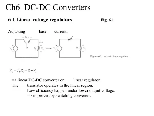
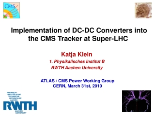
Development and System Tests of DC-DC Converters for the CMS SLHC Tracker. Lutz Feld, Rüdiger Jussen, Waclaw Karpinski , Katja Klein, Jennifer Merz, Jan Sammet ACES 2009 CERN, 3. 03. 2009. Outline. Introduction Tests with Commercial Buck Converters Tests with CERN Buck Converter

E N D
Development and System Tests of DC-DC Converters for the CMS SLHC Tracker Lutz Feld, Rüdiger Jussen, Waclaw Karpinski,Katja Klein, Jennifer Merz, Jan Sammet ACES 2009 CERN, 3. 03. 2009
Outline Waclaw Karpinski Introduction Tests with Commercial Buck Converters Tests with CERN Buck Converter Optimization of Buck Converter EMI Test Stand Material Budget Summary and Outlook
System Test with a TEC petal A typicalnoisedistribution { 1 APV Higher noiseon edgechannels (e.g. frombias ring) 6.3 6.2 6.4 6.1 Open channels Waclaw Karpinski
Commercial Inductor Based DC-DC Converters L type S type Waclaw Karpinski • Enpirion EN5312QI • switching frequency fs 4 MHz • Vin = 2.4V – 5.5V (rec.) / 7.0V (max.) • Iout = 1A • integrated planar inductor • Enpirion EN5382D (similar to EN5312QI) operated with external inductor • air-core inductor Coilcraft 132-20SMJLB (538nH) • ferrite-core inductor Murata LQH32CN1R0M23 (1H) • 4-layer PCB with 2 converters provides 1.25V and 2.5V • Input power (Vin = 5.5V) provided externally or via TEC motherboard • Various designs: type L: larger board with integrated connector, type S: smaller board with separate connector • with and w/o LDO regulator (50 mV voltage drop)
System Test with Commercial DC-DC Converters Noconverter Internal inductor Ferrite inductor • Air-coresolenoid • Air-core solenoid + LDO Pos. 6.2 radiative part conductivepart Waclaw Karpinski • internal or external ferrite core inductor: 10% noise increase • air-core inductor: huge noise increase, the noise of the edge strips increases by a factor > 10 • APV contains on-chip common mode noise subtraction • output of irregular channels is affected by this common mode subtraction: • un-bonded (low noise) channels become noisy • higher common mode on edge channels is not fully subtracted • un-bonded channels and edge channels indicate true common mode noise
System Test with Commercial DC-DC Converters Noconverter Internal inductor Ferrite inductor • Air-coresolenoid • Air-coresolenoid + LDO Pos. 6.2 radiative part conductivepart Waclaw Karpinski interference with module has two contribution: radiative and conductive “radiative part” , wing-shaped noise, can be reproduced by exposing the module to radiation from air core coil converter (not connected to a module) located above hybrid “conductive part”, comb-shaped noise, can be reproduced by noise injection into the cables LDO decreases the conductive part, but not the wings
Shielding No converterNo shielding 30 m aluminium 35 m copper • No converter Copper shield • Aluminium shield Waclaw Karpinski • radiative interference can be eliminated to a large extend by shielding the converter with 30 µm aluminum • no further improvement for > 30m • thinner shield could be sufficient • no significant difference in shielding efficiency between Cu and Al observed • contribution of 3x3x3cm3 box of 30µm alum. for one TEC: 1.5kg (= 2 per mille of a TEC)
Converter Placement • No converter • Type S‘ - 1cm • Type S‘ • Type S‘ + 1cm • Type S‘ + 4cm Type S‘ 4cm further away Waclaw Karpinski The distance between converter and FE-hybrid has been varied using a cable between converter and hybrid connector Sensitivity to distance is very high majority of noise removed over the first two cm Conductive noise is decreased as well due to filtering in the connector/cable
Low Drop-Out Regulator • Low DropOut Regulator (LDO) connected to output of EN5312QI DC-DC converter with internal coil • VLDO regulator LTC3026, 50 mV voltage dropout only • Ripple rejection 45 dB at 4 MHz • LDO reduces noise of the module significantly • The noise on edge strips is “only” a factor 2 above normal level No converter Type L without LDO Type L with LDO, dropout = 50mV No converter Type L without LDO Type L with LDO, dropout = 50mV Waclaw Karpinski
Toroid inductors • No converter • Solenoid • Toroid • Toroid + LDO • Toroid + LDO+30µm Al zoom on edge channels Waclaw Karpinski Toroid inductors radiate less power Toroid reduces the noise by factor 3 Toroid: radiative and conductive noise Toroid with LDO: radiative noise only Toroid with LDO and 30µm aluminum shield hardly any noise increase is observed
System Tests with CERN Buck Converter SWREG2 • Buck controller chip “SWREG2“ dev. by CERN electronics • group (F. Faccio et al.) in AMIS I3T80 technology • PCB with air-core coil, located far away from module • noise is conductive • SWREG2 provided 2.5V to APVs, 1.25V taken from ICB • Data recorded for Vin = 5.5V • test with several switching freq. between 0.6MHz and 1.25 MHz Waclaw Karpinski the noise level is increased by 20% noise ripple with a period of 8 strips sawtooth structure understood to be artefact of strip order during multiplexing; converter affects backend stages of APV noise performance not satisfactory
optimization of converter design 3cm • No converter • L=600nH with LDO • L=600 nH w/o LDO • L=250nH with LDO • L=250nH w/o LDO Waclaw Karpinski • focus on design of low mass, low noise shielded converters • study to improve noise behaviour • different toroids L= 600nH and L=250 nH • standard ceramic capacitors • reverse geometry low ESL capacitors • 8 terminals low ESL capacitors • with and w/o LDO • First measurements with reverse geometry capacitors
EMI Test Stand Standardized EMC set-up to measure Differential & Common Mode noisespectra (similar to set-up at CERN) Enpirion 1.25V at load Common mode fs Enpirion 1.25V at load Differential Mode Waclaw Karpinski
Noise Susceptibility Studies • Goal: identify particularly critical bandwidth(s) for converter switching frequency • Bulk current injection test-stand has been set up Waclaw Karpinski
Noise Susceptibility Studies • Injection of I=70dBA (3mA) into 2.5V, 1.25V power lines in differential/common mode • Frequency swept in the range from 0.5MHz to 100MHz • Results not quite as expected; • Peak at around 6-8MHz seen for edge strips, but not in mean APV noise • current interpretation: APV25 on-chip common mode subtraction • is again hiding the real system response 2.5V, Diff. Mode 2.5V, Diff. Mode mean noise of one APV; Deconvolution mode noise of the edge strip #512; Deconvolution mode Waclaw Karpinski
Material Budget of Buck Converter Modules and Converter • Analysis performed for the whole • strip tracker • one converter per module assumed • Official CMS software used for simulations • (CMSSW_1_8_4) Total MB of TEC modules Converters Buck Converter Design:(inspired by converter used in Aachen system tests) • Chip: 3mm x 2mm x 1mm • Board: Kapton30mm x 33mm, in total 200µm thick • 4copper layers: each 20µm thickfill factor: 2 x 100%, 2 x 50% • Coil: toroid42 windings, copper wire +plastic core • Capacitors/resistors Converter does not exist, this design was a starting point for the simulation Waclaw Karpinski
Material Budget of Buck Converter • Analysis performed for the whole • strip tracker • one converter per module assumed • Official CMS software used for simulations • (CMSSW_1_8_4) Buck Converter Design Chip Coil Capacitors and resistors Copper layers PCB/board Buck Converter Design:(inspired by converter used in Aachen system tests) • Chip: 3mm x 2mm x 1mm • Board: Kapton30mm x 33mm, in total 200µm thick • 4copper layers: each 20µm thickfill factor: 2 x 100%, 2 x 50% • Coil: toroid 42 windings, copper wire + plastic core • Capacitors/resistors • for the whole strip tracker material budged • reduction of ~8% has been estimated when powering via DC-DC converters Waclaw Karpinski
Summary Waclaw Karpinski • system test measurements with DC-DC converters have been performed • many symptoms in current test system are due to actual APV25 (and hybrid) layout • might be different for the SLHC FE ASIC • some understanding achieved • switching noise of buck converters can be controlled even with air core inductors • magnet test with 7T, converters with air-core inductors and charge pump worked fine • The ‘Task Force’ recommended DC-DC conversion as a baseline powering system for an upgraded CMS Tracking system, with Serial Powering maintained as a back-up solution • Contribution of converters to material budget is small but not negligible • for the whole strip tracker material budged reduction of ~8% has been estimated when powering via DC-DC converters
Outlook Waclaw Karpinski gain better understanding of correspondence between converter noise spectra and noise induced into the modules optimize buck converter design ; focus on low mass, low noise, shielding evaluate radiation hard converter ASIC (CERN) further tests of charge pumps follow closely the developments on serial powering continue material budget simulation: combine novel powering schemas and new cooling system (CO2)