Download
1 / 64
810 likes | 1.36k Views
ECE 506 Reconfigurable Computing http://www.ece.arizona.edu/~ece506 Lecture 4 Reconfigurable Architectures Ali Akoglu. FPGA. Introduced in 1985 by Xilinx Similar to CPLDs A function to be implemented in FPGA Partitioned into modules , each implemented in a logic block.

E N D
ECE 506Reconfigurable Computinghttp://www.ece.arizona.edu/~ece506Lecture 4Reconfigurable ArchitecturesAli Akoglu
FPGA • Introduced in 1985 by Xilinx • Similar to CPLDs • A function to be implemented in FPGA • Partitioned into modules , each implemented in a logic block. • Logic blocks connected with the programmable interconnection.
FPGA Components • Problem: How to handle sequential logic • Truth tables don’t work • Possible solution: • Add a flip-flop to the output of LUT • BLEs: the basic logic element • Circuit can now use output from LUT or from FF • Where does select come from?
FPGA Components • Example: 8-bit register using 3-input, 2-output LUTs • Input: x, Output: y 3-in, 2-out LUT FF FF
FPGA Components • Example: 8-bit register using 3-input, 2-output LUTs • Input: x, Output: y • What does LUT need to do to implement register? x(7) x(6) x(5) x(4) x(2) x(1) x(0) x(3) 3-in, 2-out LUT 3-in, 2-out LUT 3-in, 2-out LUT 3-in, 2-out LUT FF FF FF FF FF FF FF FF y(7) y(6) y(5) y(4) y(3) y(2) y(1) y(0)
FPGA Components • LUT simply passes inputs to appropriate output Inputs/Outputs LUT functionality x(1) x(0) x(1) x(0) 3-in, 2-out LUT FF FF FF FF y(1) y(0) y(1) y(0)
FPGA Components • LUT simply passes inputs to appropriate output Inputs/Outputs LUT functionality x(1) x(0) x(1) x(0) 3-in, 2-out LUT FF FF FF FF y(1) y(0) y(1) y(0)
FPGA Components • Isn’t it a waste to use LUTs for registers? • YES! (when it can be used for something else) • Commonly used for pipelined circuits • Example: Pipelined adder 3-in, 2-out LUT 3-in, 2-out LUT + + . . . . Register Register FF FF FF FF + Adder and output register combined – not a separate LUT for each Register
FPGA Components • Configurable Logic Blocks (CLBs) usually contain more than 1 BLE • Why? • Efficient way of handling common I/O between adjacent LUTs • Saves routing resources 2x1 3-in, 2-out LUT 3-in, 2-out LUT CLB FF FF FF FF 2x1 2x1 2x1 2x1
FPGA Components • Example: Ripple-carry adder • Each LUT implements 1 full adder • Use efficient connections between LUTs for carry signals A(0) B(0) Cin(0) A(1) B(1) Cin(1) 2x1 3-in, 2-out LUT 3-in, 2-out LUT CLB FF FF FF FF 2x1 2x1 2x1 2x1 Cout(0) S(0) Cout(1) S(1)
FPGA Components • On real FPGAs: a cluster of LUTs per switch matrix (e.g., eight LUTs and switch matrix form a configurable logic block on Xilinx FPGAs)
Typical CLB • The arithmetic logic provides • XOR-gate and faster carry chain to build faster adder without wasting too much LUT-resources.
Xilinx CLBs • Macro cells are CLBs. • The number of basic blocks in a CLB varies from device to device. • 4000, Virtex, Virtex E, Spartan: 1 slice, 2 basic blocks • Spartan 3, VirtexII, Virtex II-Pro Virtex 4: 4 slices, 2 basic blocks/slice • Virtex 5: • 2 slices, 4 basic blocks/slice
Xilinx CLBs • Left part slices of a CLB (SLICEM) • configured either as combinatorial logic or SRAM or shift register • SLICEL • only to be configured as combinatorial logic. • Each BLE • 4 inputs and 1 output • Spartan 3, VirtexII, Virtex II-Pro Virtex 4: 4 slices, 2 basic blocks/slice
Xilinx CLBs • LUT has 6inputs and 2outputs. • LUT can be configured either as • a 6-input LUT, in which case only one output can be used, • or as two 5-input LUTs, two outputs used • Virtex 5: • 2 slices, 4 basic blocks/slice
Xilinx Virtex6 CLB • A CLB contains 2 identical slices on Virtex 6 • 2 slices are split in two columns of 1 slices each • 1 slice contains: • 4x 6-inputs LUT • 8x FF for storing LUT results • MUX to feed LUT either to a FF or the output • Carry in and carry out to construct fast adder using neighbor CLBs
Altera FPGA Basic Blocks • Altera’s FPGAs (Cyclone, FLEX) • basic unit of logic is the logic element (LE) • also LUT-based • a 4-LUT, a flip flop, a multiplexer and additional logic for carry chain • LEs can operate in different modes each of which defines different usage of the LUT inputs. • Altera LEs • grouped into logic array blocks (LAB). • Flex 6000 LAB contains 10 LEs • FLEX 8000 LAB contains 8 LEs. • Cyclone II LAB contains 16 LEs
Altera FPGA Basic Blocks • StratixII • basic computing unit is called adaptive logic module (ALM) • Each LAB contains 8 ALMs • ALM can be used to implement functions with variable number of inputs. • Ensures a backward compatibility to 4-input-based designs, • Possible to implement module with up to 8 inputs. • Additional modules: including flip flops, adders and carry logic
FPGA Components • CLBs often have specialized connections between adjacent CLBs • Further improves carry chains • Avoids routing resources • Basic building block is CLB • Can implement combinational+sequential logic • All circuits consist of combinational and sequential logic • So what else is needed? • FPGAs need some way of connecting CLBs together • Reconfigurable interconnect • But, we can only put fixed wires on a chip
FPGA Components • Problem: If FPGA doesn’t know which CLBs will be connected, where does it put wires? • Solution: • Put wires everywhere! • Referred to as channel wires, routing channels, routing tracks, many others • CLBs typically arranged in a grid, with wires on all sides CLB CLB CLB CLB CLB CLB
FPGA Components • How to connect CLB to wires? • Solution: Connection box • Device that allows inputs and outputs of CLB to connect to different wires Connection box CLB CLB
FPGA Components • Connection box characteristics • Topology • Defines the specific wires each CLB I/O can connect to • Examples: same flexibility, different topology CLB CLB CLB CLB
FPGA Components • Connection boxes allow CLBs to connect to routing wires • But, that only allows us to move signals along a single wire • Not very useful • How do FPGAs connect wires together?
FPGA Components • Solution: Switch boxes, switch matrices • Connects horizontal and vertical routing channels • But, we can only put fixed wires on a chip CLB CLB Switch box/matrix CLB CLB
FPGA Components • Switch boxes • Flexibility - defines how many wires a single wire can connect to • Every possible connection? • Too big • Too slow
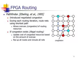
FPGA Components • Why do flexiblity and topology matter? • Routability: a measure of the number of circuits that can be routed • Higher flexibility = better routability • Wilton switch box topology = better routability Src Src CLB CLB No possible route from src to dest Dest Dest
FPGA Components • Many Topologies possible • Fs= 3 is common 0 1 2 3 4 5 6 0 1 2 3 4 5 6 0 1 2 3 4 5 6 0 1 2 3 4 5 6 Disjoint Wilton Universal • Topology - defines which wires can be connected
FPGA Components 0 1 2 3 4 5 6 • Disjoint: a wire entering can only connect to other wires with the same numerical designation. • potential source–destination routes in the FPGA are isolated into distinct routing domains, limiting routing flexibility. • Wilton: uses same number of routing switches but overcomes the domain issue • By allowing for a change in domain assignment on connections that turn. • ability to change domains in at least one direction facilitates routing as a greater diversity of routing paths from a net source to a destination is possible. 0 1 2 3 4 5 6 0 1 2 3 4 5 6 0 1 2 3 4 5 6 G. Lemieux and D. Lewis, “Circuit design of routing switches,” in Proceedings: ACM/SIGDA International Symposium on Field Programmable Gate Array, pp. 19–28, February 2002. G. Lemieux and D. Lewis, Design and Interconnection Networks for Programmable Logic. Boston, MA: Kluwer Academic Publishers, 2004.
FPGA Components • At each switch block: some tracks end some tracks pass right through
FPGA Components • Switch boxes • Short channels • Useful for connecting adjacent CLBs • Long channels • Useful for connecting CLBs that are separated • Allows for reduced routing delay for non-adjacent CLBs Medium Short Long
FPGA Components • FPGA layout called a “fabric” • 2-dimensional array of CLBs and programmable interconnect • Sometimes referred to as an “island style” architecture
FPGA and Data Storage • Solution 1: Use LUTs for logic or memory • LUTs are just an SRAM • Xilinx refers to as distributed RAM • Solution 2: Include dedicated RAM components in the FPGA fabric • Xilinx refers to as Block RAM • Can be single/dual-ported • Can be combined into arbitrary sizes • Can be used as FIFO • Different clock speeds for reads/writes
FPGA Components • Fabric with Block RAM • Block RAM can be placed anywhere • Typically, placed in columns of the fabric BR CLB CLB BR CLB CLB . . . BR CLB CLB BR CLB CLB BR CLB CLB BR CLB CLB . . . .
FPGA Components • FPGAs commonly used for DSP apps • Makes sense to include custom DSP units instead of mapping onto LUTs • Custom unit = faster/smaller • Example: Xilinx DSP48 • Starting with Virtex 4 family, Xilinx introduced DSP48 block for high-speed DSP on FPGAs • Essentially a multiply-accumulate core with many other features • Provides efficient way of implementing • Add/subtract/multiply • MAC (Multiply-accumulate) • Barrel shifter • FIR Filter • Square root
FPGA Components • FPGAs are 2-dimensional arrays of CLBs, DSP, Block RAM, and programmable interconnect • Actual layout/placement differs for different FPGAs BR DSP DSP BR DSP DSP BR CLB CLB BR CLB CLB BR CLB CLB BR CLB CLB BR CLB CLB BR CLB CLB . . . .
FPGA Components Xilinx Virtex II Pro FPGA
Spartan3 Components Spartan 3
Virtex7 FPGA DSP48 DSP48E1 Tile (Two DSP48E1 Slices and Interconnects)
Virtex7 FPGA DSP48 • Single-instruction-multiple-data (SIMD) arithmetic unit: • Dual 24-bit or quad 12-bit add/subtract/accumulate • Cascading capability on both pipeline paths for larger multipliers and larger post-adders
Programming FPGAs • Mapping a circuit onto FPGA fabric • Known as technology mapping • Process of converting a circuit in one representation into a representation that corresponds to physical components • Gates to LUTs • Memory to Block RAMs • Multiplications to DSP48s • Etc. • But, we need some way of configuring each component to behave as desired • Examples: • How to store truth tables in LUTs? • How to connecting wires in switch boxes? • Etc.
Programming FPGAs • FPGAs programmed with a “bitfile” • File containing all information needed to program FPGA • Contains bits for each control FF • Also, contains bits to fill LUTs • But, how do you get the bitfile into the FPGA? • > 10k LUTs • Small number of pins
CLB CLB CLB CLB CLB CLB CLB CLB CLB CLB CLB CLB Programming FPGAs • Solution: Shift Registers • General Idea • Make a huge shift register out of all programmable components (LUTs, control FFs) • Shift in bitfile one bit at a time Configuration bits input here Shift register shifts bits to appropriate location in FPGA