Download
1 / 12
120 likes | 268 Views
EMC DCS Status. 6. March 2007. KEY DATES. Installation EMC frame in L3: May 07 1st Detector module early 2009 Validation of DCS in Testbeam Summer 2007 A more detailed commissioning meeting will be held closer to the installation of the first detector module. EMC. 4. 2. 24. 1. 1.

E N D
EMC DCS Status 6. March 2007 EMC DCS Status
KEY DATES • Installation EMC frame in L3: May 07 • 1st Detector module early 2009 • Validation of DCS in Testbeam • Summer 2007 • A more detailed commissioning meeting will be held closer to the installation of the first detector module. EMC DCS Status
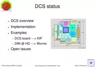
EMC 4 2 24 1 1 64 2 32 24x2 + 24x2 sense 2 bundles of 37 1 396 2 1 24 4 10/8/06 [UI node] Database(s) PVSS II PVSS II PVSS II Control room (ACR) OPCclient DIMclient User interface Ethernet PVSS II PVSS II PVSS II PVSS II PVSS II PVSS II OPC client OPC client DIMclient ? OPC client ISEG OPCserver Wiener OPCserver ELMB OPCserver PCI-CAN E USB-CAN C C E E ISEG HV Shared Cooling Water Subsystem Wiener Netgear switch E LV LED ELMB DDL RCU DIMsrv BiasVR Optical Fiber Detector Detector Detector Detector Detector EMC DCS Status High Voltage Low Voltage FEE LED calibration Temp. Monitor Cooling
High Voltage • PVSS: Some work was done by Creighton group last summer. First use of Iseg FW component on HW in DCS lab. Strasbourg group will develop this system • FSM: Not started • HW: Strasbourg group purchased 1 Iseg crate. EMC DCS Status
Low Voltage • PVSS: Some work done at Creighton. • FSM: Not started • HW: Borrowed unit available. 4 Wiener LVPS to be purchased, at least 6 months delivery delay to be counted with. EMC DCS Status
RCU and Bias • PVSS: Not complete. Some work on the underlying layers (on FEE server) was done last summer and fall by the Creighton group, in collaboration with PHOS (Per-Thomas Hille). PVSS interface for prototype board in PVSS 3.1. • Configuration: Collaboration was proposed and agreed between PHOS and EMC on this subject. • FSM: Not started • HW: Prototype board at Brookhaven EMC DCS Status
LED calibration system • Hardware system not yet designed. • Critical Item. EMC DCS Status
Temperature Monitor (ELMB) • PVSS: Some work was done last summer by the Creighton group. They used the ELMB FW component with the ELMB hardware in the DCS lab. Setup currently at Creighton. PVSS uses 3.1. • FSM: Not started • HW: 4 ELMBs (2 on each side) are foreseen, with around 120 sensors. Communication problemsencountered. EMC DCS Status
Cooling • Connected to TOF/PHOS/CPV cooling plant; available now. EMC DCS Status
Detector DCS FSM • Prototype FSM created. • Not integrated to hardware. EMC DCS Status
Installation at P2 • Only the EMC frame will be installed. On the frame the ELMBs will be mounted and cabled up. All should be ready to be mounted end this week. • Interlocks: • 1 interlock from cooling to LV. • 2 pressure sensors like PHOS/TPC to stop cooling plant in case of leak (read by DSS). EMC DCS Status
ITS Alignment System • Use PC (Windows) Front End • PVSS 3.1 interface constructed • No FSM planned • Current system captures image and compares with stored image EMC DCS Status