Download
1 / 43
470 likes | 665 Views
Designing Small, Simple and Efficient DC to DC Converters. Andy Cowell Applications Manager Asia Feb 2004. MICREL’S DC to DC Converters. SMALL SIMPLE and EFFICIENENT Small Any DC to DC converter must be as small as possible for the given application Simple

E N D
Designing Small, Simple and EfficientDC to DC Converters Andy Cowell Applications Manager Asia Feb 2004
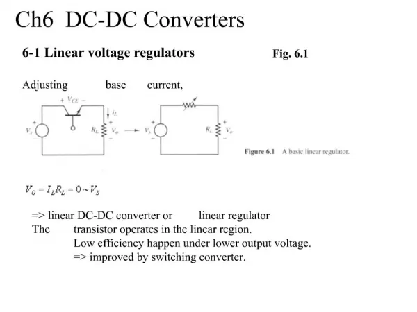
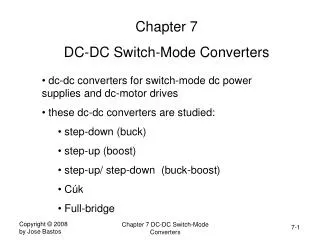
MICREL’S DC to DC Converters • SMALL SIMPLE and EFFICIENENT • Small • Any DC to DC converter must be as small as possible for the given application • Simple • The DC to DC converter must use as few external components as possible, without sacrificing performance • Efficient • The DC to DC converter must be highest efficiency to minimize any losses
The Issues – making a DC-DC Small • The biggest component of a DC to DC converter are the Inductor L, and the Capacitance C • Increasing the switching frequency decreases the size of L and C, but decreases the Efficiency. • The DC to DC converter must have high speed loop response to keep the output voltage stable under all conditions with a small value of L and C
The Issues – Making a DC-DC Simple • To make a DC to DC converter simple all the stability components need to be inside the Integrated Circuit • The DC to DC converter needs to have high loop speeds without any external components to keep the L and C small
The Issues – Making a DC-DC Efficient • The DC to DC converter needs to have a high switching frequency to keep the L and the C small • As the switching Frequency increases the switching losses increase, making it less efficient • Note Switching Power Loss in a MOSFET device used in most DC to DC converters , Is proportional to Mosfet gate charge ,Q, x Gate Voltage, Vgs, x Frequency, f • A new drive scheme is needed to minimize switching losses
2MHz PWM Synchronous Buck Regulator 2.2mH Output down to 0.5V 600mA 2.3V to 5.5V Input 1mF 2.2mF PWM Regulator with World’s Smallest LC • Industry’s Smallest Output Components • Ultra-fast transient response • Over 95% efficient • Tiny MSOP-10 and 3mm x 3mm MLF-10L
MIC2202 Benefits • Small • Tiny 2.2mH inductor and 1mF capacitor (…or visa-versa, 1mH inductor and 2.2mF capacitor!! ) • Few external components • 3mm x 3mm MLF package has same pcb area as SOT23 • 4x better thermal performance than SOT23 • Low Noise • No variable frequency modes of operation • MIC2202 always operates in fixed frequency PWM mode • Ideal for noise sensitive applications • RF and high speed communications systems
MIC2202 Benefits • FAST! • Up to 500KHz closed loop band width • Fast transient response allows smaller COUT • Ideal for applications that need fastest response • DAC-controlled VOUT applications such as CDMA RF Power • Efficient • >95% efficient • Proprietary gate drive minimizes shoot-through current
How the MIC2202 can use small values of L and C • The 2Mhz switching frequency keeps the L and C Low. • To Reduce the L and C to Only 2.2uH and 1uF output Capacitor, a very high loop bandwidth was required. • Traditionally a tantalum output capacitor is required to add an extra zero into the loop to help stabilize. • The MIC2202 uses a 1uF ceramic output capacitor to reduce size A new compensation scheme is needed to achieve high stable bandwidths
MIC2202 Ultra high Bandwidth loop compensation ULTRA HIGH BW
MIC2202 Performance: L = 2.2mH , COUT = 1mF Excellent Load Transient Response Switching Waveforms
High Efficiency with MIC2204 High Efficient drive scheme reduces switching losses
MIC2202 Inductor Selection versus Efficiency • 2.2mH is optimal inductor value for small size and high efficiency • MIC2202 works with as low as 1mH inductor for the smallest size • Up to 4.7mH inductor for reduced ripple current and higher light load efficiency.
MIC2202 Eval Boards • 2 evaluation boards are available: • MIC2202BMM EV (MSOP-10 package) • MIC2202BML EV (3x3 MLF package) VIN VOUT 1cm x 1.3cm pcb area
MIC2202 Applications • 802.11 WLAN power supply • Camera / video chip power • Cellular phones • PDAs • Digital cameras • CDMA Dynamic VOUT RF Power Amp power supply • Wireless and DSL modems • Storage drives • CD/DVD ROM power • PHY core and I/O power supply • ASIC / FPGA / DSP / CPU power supply • Portable applications
A High Power Guide to the World of Low Power DC to DC Converters Andy Cowell Applications Manager Asia Email andrew.cowell@micrel.com Tel +64 6 378 9799 WWW.MICREL.COM
Technical Sheet – Buck Converter Buck - Technical Sheet
Micrel Part number. Feature Synchrous Buck? External Switch(es) required Switching Frequency Input Voltage (Volts DC) Output Current Min Output voltage MIC2202/4 ** Ultra small L and C for up to 600mA out YES No 2 MHz 2.7 to 5.5V 50mA-600mA 0.5V MIC2168/9 ** Small size Buck controller YES YES 1Mhz/500kHz 3 to 14V 500mA-20A 0.8V MIC4680/4 ** Small Simple NO NO 200kHz 4.5-34V 1-1.5A 1.25V MIC4685 Small Simple NO NO 200kHz 4.5V-32V 3A 1.25V MIC2193/4 Low voltage SO-8 controller YES YES 400Khz 2.9V-14V 500mA-10A 1.25V MIC2183/4 Flexable SO-16 Controller Ics YES YES 200/400KHz 2.9V-14V 500mA-10A 1.25V MIC2198/9 Utra small High voltage Buck YES YES 200/400Khz 4.5-32V 500mA-20A 1V MIC2182 Controller with light load mode YES YES 200Khz 4.5V to 32V 500mA to 20A 1.25V Selector Guides ** Most popular
MIC2168/9 Simple Synchronous Buck Controllers • 3VIN to 14.5VIN • VOUT down to 0.8V • 500KHz fixed frequency PWM (MIC2169) • 1MHz fixed frequency PWM (MIC2168) • Up to 97% efficiency • No sense resistor • Output over-voltage protection • Adaptive gate drive VIN RSET VOUT
MIC2168/9 Features • Wide 3V to 14.5 operating range • Works from 3.3V, 5V, and 12V power busses • Internal bootstrap allows single supply operation • Other solutions require split supply operation • VOUT range 0.8V to 12V; IOUT up to 20A • Powers the latest ICs • Adaptive gate drive • Allows up to 97% efficiency • Prevents shoot-through current • High-side n-channel MOSFET current sensing • No current-sense resistor saves cost and efficiency
MIC2168/9 Features • Dual mode current limit allows fastest recovery time • Hard current limit until VOUT drops ~16% • Hiccup current limit after VOUT drops below 16% (output short-circuit protection) • Output over-voltage protection • Protects system downstream in fault conditions • Hysteretic transient recovery mode • Allows ultra-fast transient response • Internal soft-start • Reduces in-rush current • Dual function COMP / EN pin • Pull this pin to ground for low power shutdown mode • Flexible architecture • Tantalum capacitor capable for most applications • All-ceramic capacitor capable for smallest size • Electrolytic capacitor capable for lowest cost
MIC2168/9 Applications • Point-of-Load DC/DC Conversion • Telecom/Networking/Datacom systems • DSP / CPU / FPGA / ASIC power supplies • Set top boxes • Graphics Cards • LCD Power Supplies • Cable modems • HDD and tape drives • DC/DC SIP modules
MIC2168 versus MIC2169 • MIC2168 (1MHz) • Use for smallest size applications • 1MHz operation allows smaller external inductor • The trade off with higher frequency is slightly less efficiency (up to ~3-5%) and lower output current • MIC2168 is optimal for < ~5A applications • MIC2169 (500KHz) • Use for highest current applications that require the most efficiency
MIC2169 Proprietary Adaptive Gate Drive • Typical dc/dc controllers sacrifice efficiency by having a long fixed dead time between the high- and low-side MOSFET drivers to prevent shoot-through current. The dead time needs to account for maximum MOSFET gate capacitance. Though it prevents shoot-through, efficiency is lost during the low-side MOSFET parasitic diode or external Schottky diode conduction time. • The MIC2168/9 self-adjusts the dead-time from 30ns to 100ns to maximize efficiency and prevent shoot-through VIN VOUT No Shoot-Through!
MIC2169 Internal Soft Start • Turn on characteristic, VOUT rise time: 2ms rise time Reduces in-rush current
MIC2169 Output Over-Voltage Protection • Output OVP protects load in fault conditions • eg: solder-bridge in assembly, or if high-side NFET fails short • Low-side NFET turns on during output OVP conditions • Blows input fuse to protect the expensive downstream load (1A current limited for benign test) OVP Test Inductor Current sinking 1A OVP Test Circuit: Switch High Voltage to MIC2169 Output
MIC2169 All Ceramic Capacitor Circuit VIN 5V VOUT 3.3V 4A
MIC2169 Ceramic Circuit Bode Plot STABLE!54 Phase Margin 29kHz cross-over frequency
MIC2169 7A Eval Board • Available on on-line sample order system 1.75” 4.5cm VIN MIC2169 CIN VOUT selector jumpers 2” 5cm N-Channel MOSFETs Inductor COUT VOUT TOP BOTTOM
MIC2169 7A General Purpose Eval Board VIN 5V to 12V VOUT (Jumper Adjustable) Shut Down (optional) * (optional) * * Light snubbing is required for super low duty cycle applications to maintain accurate current limiting (ex: 12VIN to 1VOUT applications) . These components can be removed for applications with higher duty cycle.
MIC2169 Eval Board Performance • Eval Board Efficiency Eval Board supports 10A with airflow, 7A without. Current is limited by the PCB thermals
MIC2169 Eval Board Bode Plot (12VIN to 3.3VOUT ) STABLE!64 Phase Margin 26kHz cross-over frequency
Technical Sheet – Boost Converter Boost - Technical Sheet
Micrel Part number. Feature Synchronous Boost? External Switch(es) required Switching Frequency Input Voltage (Volts DC) Output Current Max Output voltage MIC2288 ** Small SOT23 Package, high output power NO NO 1.2 MHz 2.5- 10V Up to 500mA 34V MIC2290 ** 2288 with internal schottky diode YES NO 1.2MHz 2.5V- 10V Up to 300mA 34V MIC2196 ** Small Simple in SO-8 NO YES 400kHz 2.9V-14V 5A+ >50V MIC2171 High power Boost with internal switch NO NO 100Khz 3.0V-40V 3A 60V MIC2185/6 Flexable SO-16 Controller Ics YES YES 200/400KHz 2.9V-14V 5A+ >50V MIC2145 High Power MSOP-8 NO NO 450Khz 2.2V-14V Up to 700mA 18V MIC3171/2 High voltage simple SO-8 NO NO 100Khz 3V - 40V 500mA 60V MIC2141/2 Small SOT23 NO NO 330kHz 2.7-16V to 100mA 18V Selector guide- Boost ** Most popular
MIC2288 Boost Regulator • 2.5V to 10VIN • 1.2MHz fixed frequency PWM • >1A switch current • Up to 34VOUT • Tiny 2x2mm MLF-8L and Thin SOT23-5L package options OEL Driver
MIC2288 Boost Regulator L = 10mH COUT = 10mF
MIC2288 Boost Regulator VOUT <0.35%!!!
MIC2288 Load Transient Performance 12VOUT 150mA 50mA L = 10mH COUT = 10mF VOUT <0.25%!!!
MICREL DC to DC Converters For Small Simple Efficient DC to DC Converters Think MICREL