Download
1 / 46
500 likes | 740 Views
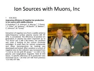
Electrical Hazards and Safety with Ion Sources. Martin P. Stockli Spallation Neutron Source Oak Ridge National Lab. Oak Ridge, TN 37830. Prologue. 40 mA minimum current during a 1.23 ms long pulses! >50 mA peak current 340 A antenna current!.

E N D
Electrical Hazards and Safety with Ion Sources Martin P. Stockli Spallation Neutron Source Oak Ridge National Lab Oak Ridge, TN 37830
Prologue • 40 mA minimum current during a 1.23 ms long pulses! • >50 mA peak current • 340 A antenna current! This are exiting times! Thanks to new controls we are now able to fine tune the source on the hot spare stand to the parameters needed for full operations in 2009!
Content • High Voltage Requirements • High Voltage Problems • High Voltage Platforms • Very High Voltage Platforms • Small High Voltage Platforms • Intermediate High Voltage Platforms • The SNS High Voltage Platform • The SNS Ion Source Hazards • The SNS Ion Source Safety Measures
Introduction • Ion sources are not a consumer product. • Only a few are produced in small series for industrial equipment such as ion implanters, leak detectors, etc. • Most ion sources are prototypes, designed and built to meet very specific applications. • Ion sources are not specifically regulated, but as electrical equipment, they are subject to electrical safety regulations. They regulate: Voltages > 50 V and currents > 5 mA or stored energies > 10 J True for practically all ion sources True for high current sources True for high current sources This presentation focuses on electrical hazards and safety for ion sources, especially for high current ion sources (> 5mA).
Electric Hazards • Electric hazards increase rapidly with voltage. For facility power, the voltage classifies the hazard. 1,000,000 100,000 10,000 1,000 100 10 1 • However, what happens when things go wrong, depends on the current, over which we have only limited control. • Whenever possible, the current shall be limited to safe levels by fuses, circuit breakers, resistors, GFCI, etc. • R&D devices often do not allow for safe limits. Their hazard classification depends on voltage and current capability. >500 V: very dangerous (skin puncture) Voltage [V] safe < 50V
R&D Electric Hazard Classifications or > 10 J arc flash 250 V burn injury 500 A 1000 VA and < 10 J electric shock safe 50 V 5 mA reflex 1000 VA Current [A] Voltage [V]
Ion Beam Formation Extraction gap d z E - HV supply +V Ion sources require an electric field to accelerate the ions in an uniform fashion that forms a laminar beam. In the absence of charged particles the electric field is uniform E=V/d, with the ion source voltage V and the extraction gap d. When charged particles are present, their space charge modifies the electric field up to E ~ (z/d)1/3 V. The low field for small z limits the the number of particles that are accelerated. This limits the ion beam current density j to j ~ V3/2/d2. High voltages enable the production of high current ion beams! The extraction gap has to be operated near the breakdown limit. Occasional arcing is unavoidable for high current ion beams.
Low Energy Beam Transport Ionized residual gas neutralizes the ion beam. This neutralization can be difficult to control (e.g. in magnetic fields, choppers, etc.). When partly neutralized ion beams are transported, the space charge of the (non-neutralized) beam pushes the particles towards larger radii, causing an undesirable growth of the ion beam diameter. The SNS accelerator has a short, electrostatic LEBT to minimize the ion beam neutralization and the undesirable growth! The space charge of the ion beam is proportional to the density of the particles, which is indirectly proportional to the ion velocity. By increasing the beam energy by a factor of 4, the space charge can be reduced by a factor of 2. High current ion beams need high voltage!
SNS Requirements for the Ion Source and LEBT • Ion Specie H¯ • Pulse Current at source ~50 mA • Beam Energy 65 keV • Rep Rate 60 Hz • Pulse length 1.3 ms trimmed to 1.0 ms • RMS Emittance 0.2 mmmrad • Droop & Noise during single pulse minimal • Pulse to Pulse Variations minimal • Operation time between m maintenance several weeks • Mean time between failures many months >> 5 mA >> 50 V The SNS ion source is a significant electrical hazard!
The SNS Ion Source • Plasma generation: • 15-40 sccm Hydrogen gas • 13.56 MHz RF, typically 150 W continuous (supply: 600 W) • 2 MHz 50 kW RF pulsed at 60 Hz / 1.3 ms (supply: 80 kW peak) • Plasma confinement: • Multicusp ~ 0.25T • radial 20 magnets • axial 4 magnets • Negative ion formation: • 200 Gauss transverse filter field • 10 0.5 mg Cesium cartridges that need to be heated to ~ 500C to release Cs Ions The SNS ion source contains several hazards, but we focus on HV
The SNS Ion Source High Voltage Platforms SNS has two operational ion sources: The Front-End ion source feeds the SNS accelerator. The Ion Source Hot Spare Stand is an (almost) identical copy of the Front End ion source and LEBT, and is fully functional. Besides being a complete set of hot spares, the stand is used to test and develop the SNS ion source. Front-End Hot Spare Stand Front-End Building
Low Energy Beam Transport 10 keV protons V = -20 kV Electrostatic focusing depends on a significant change of the ion energy. Decel-accel lenses have significant aberrations due to beam size. 10 keV protons V = +7 kV Technical high voltage problems limit the use of accel-decel lenses to low voltage ion sources (few 10s of kV). The compact SNS LEBT uses decel-accel lenses that reduce the beam energy by a factor of ~3!
Low Energy Beam Transport - HV Problems Load current I output Voltage V Power- switch and Decoupling network Multiplier, Rectifier, and Filter Ri Ideal Operational Range AC input Pulse-width Modulator Load current I Programming Inputs Return V=IRi V=IRe Voltage V Voltage V Imax Operational Range with Pre-load Resistor Real Operational Range Re Load current I Load current I Electrostatic focusing of high voltage beams requires the same polarity voltage as the beam. HV supplies are designed to source current. They can sink only a very small current through the feedback resistor. When a part of the beam hits a decel-accel lens, the voltage will rise quickly according to IRi. Adding a significantly lower ohm load resistor (Re<<Ri) to the output extends the range where the supply can sink current up to Imax = V/Re.
Low Energy Beam Transport - HV Problems - - - • 3 kV 33 mA supply • 3 kV 33 mA supply • 3 kV 33 mA supply • 3 kV 33 mA supply - - Ey - d Ex Lens 2 supply ~ 45 kV Rs Rs Rc Cc EPICS +3 kV 400 mA supply HV pulser HV pulser Quad Gate Driver - 3 kV 400 mA supply HV pulser HV pulser However, for lens 2 of the SNS LEBT, preloading is not an option because of the integrated chopper. The high voltage of the 4 lens segments are modulated by the HV pulsers through the HV blocking filters RcCc . Warning: The voltage of beam transport elements may be higher than you think!
The advantage of RF sources - + - + - + - + - + battery B E I • The 1st Maxwell Equation: E = ρ/єo states that electric fields are generated by any free net charges and the easy controllable surface charges ρ on electrodes. This explains the need for the surface charges to generate the ionizing electric field. As the negative surface charges attract positive ions the sputtering problem appears unavoidable. E - + • The 2nd Maxwell Equation, however,xE = - ∂B/∂t describes a curling E field generated by a changing magnetic field in the absence of any charge! A changing magnetic field B can be produced in N windings with radius ro with an alternating current i = io•cos(ωt) : B = ½•µo•N•i/ro (Biot-Savart). Now integrate Maxwell’s 2nd equation for Faraday’s law: ∫E•ds= -dΦB/dt = -d/dt ∫B•dA and solve for E: E(r<ro,t)= ¼•r/ro•µoωN•io•sin(ωt) Sputtering greatly reduced! This is a circular electric field that bites its own tail rather than a poor electrode!
Matching an RF driven ion source ANTENNA CURRENT versus CAPACITANCE NP L 2.00 MHz L = 10.55 µH 0.4 ohms 0.5 ohms 0.7 ohms NS INVERSE IMPEDANCE [A/V] C RS Current lags CAPACITANCE [nF] PHASE SHIFT Current leads •The antenna current is maximized by matching the RF amplifier output impedance with the impedance of the antenna circuit by adjusting the transformer ratio NS/NP. •The antenna current is maximized by tuning the RLC circuit to its resonance. The resonant frequency is ω2= (LC)-1 and the impedance is Z=Єo/io=(R2+(ωL-(ωC)-1)2)½ •With L ≈ 10 µH and ω ≈ 2π2 MHz, C needs to be tuned to ~0.6 nF to obtain the maximum current io=Єo/R. • Experience lead to increasing C to ~2 nF, while reducing L to ~ 3 µH.
Matching an RF driven ion source NP L NS C RS •The antenna current is maximized by tuning the variable capacitor CVDP-2300-15S by Jennings. •A 40 mA MEBT beam requires ~45 kW RF, yielding a 300 A peak antenna current. This corresponds to 212 A RMS, near the cap’s current limit! • For a resonant 300A peak current the peak voltage over the components is V0 = Zi0 = i0/(C) = i0L: • The ~2.3 nF capcitance on the hot spare stand are safe, while the ~1.5 nF capcitance on the front end tests the high voltage limit of the capacitor!
Low Energy Beam Transport - HV Problems Ion optical elements, such as lenses, and diagnostic elements, such as Faraday cups, can be charged up by the ion beam, up to the voltage of the ion beam. The stored energy increases with the voltage. It is E = CU2/2. The (stray) capacitance of disconnected elements is small, few 10s of pF. Therefore the maximum stored energy is always less than 10 J. The average SNS beam current is < 50 mA8% d.c. = 4 mA and hence not a life endangering electrical hazard. Faraday cupsand/or disconnected ion optical elements can give you an unpleasant jolt, but you will stay around to figure out what happened.
Low Energy Beam Transport - HV Problems This, however, is not the case when elements are connected to the high voltage supplies! High current ion beams require high current supplies that are dangerous!
R&D Electric Hazard Classifications or > 10 J arc flash 250 V burn injury 500 A 1000 VA and < 10 J electric shock chopper safe 50 V e-dump extractor streerer lenses 5 mA reflex 1000 VA Ion source platform matching network Current [A] Voltage [V]
Effects of Stored Electrical Energy When failures occur, the high voltage platform inside the Big Blue Boxes can be very dangerous. Entry requires training. LOTO is equipment specific and requires training and certification.
A spare for the SNS 65 kV supply The Front End features a custom built DTI 150 mA, 70 kV supply • V/V 0.3% achieved with a 0.5 F output capacitor (75mA,1.3ms) • an arc detector triggered a fast HV switch to decouple ~ 1000 J stored energy • this fast HV switch became permanently conductive at LBNL • DTI estimate for more reliable switch: k$ 50 • DTI estimate for replacing failed switch: k$ 20 • Paid DTI to remove failed switch: k$ 10 • Off-the-shelf 80 kV fast switch from Behlke k$ 2.7 Some R&D is required to integrate the Behlke switch. Operation without a fast switch is likely to contribute to sparks that upset control units. We have beefed up the high voltage robustness, which dramatically decreased the spark rate. But a spare supply is needed! DTI estimate for a spare supply: k$ 150
A Spare for the 65 kV Supply The Hot Spare Stand features a k$ 15.2 off-the-shelf Glassman 110 mA, 70 kV supply • its 10 nF output capacitor stores only about 20 J • voltage drops ~750 V/s at the start of each extraction (75 mA) • voltage recovers after ~ 0.5 ms • Possible solutions: • Start source 0.5 ms early • (increases source duty cycle) • Add 0.5 F & fast switch • (requires some R&D) • Use feed forward technique to reduce voltage excursions • Speed up feedback circuit The latter solutions provide a significantly safer system!
High Voltage Platforms The generation of ions requires the operation of power supplies to heat filaments and/or to generate a plasma, to control flow valves, etc. In addition, proper operations requires monitoring voltages, currents, temperatures, etc. All this equipment has to be connected to the ion source that is at high voltage, requiring a high voltage platform. • Depending on the high voltage and the size of components, high voltage platforms can be categorized into 3 groups: • Small high voltage platforms: < 100 kV; small components • Intermediate high voltage platforms: < 300 kV • and/or large components • Very high voltage platforms: > 500 kV
High Voltage Platforms ~25 kV/cm in 1 atm air
Very High Voltage Platforms Very high voltage platforms (> ~500 kV) require a full metal enclosure of the platform and full metal coverage of the ground. Intermediate corona rings are needed to control and limit variations of the high voltage gradient. The radius of the corona guards need to be large enough to keep the fields significantly below 25 kV/cm. Bare metal walls drain the corona charges.
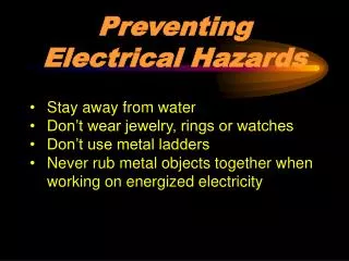
Small High Voltage Platforms Small components subject to <100 kV, can be enclosed in a plastic box containing a isolation transformer and the power supplies needed to operate an ion source. The box should also contain all load resistors, limiting resistors, and monitors that need to operate at high voltage. The box has to be finger safe, meaning that it is safe to touch the box and all connections at any place, at any time! The cables connecting the box to the source need to be rated for the maximum voltage, e.g. Vmax = Vplatform+ Varc Axial PIG ion source developed at IFK, Frankfurt U., and sold by NEC Small ion sources are normally of little concern because they employ <5 mA supplies !
Small High Voltage Platforms • To be finger safe, one needs to prevent under all conditions all • Arcing through the enclosure • Arcing along the surface of the enclosure Spellman High Voltage recommends: < 3.3 mm (0.13”) per kV air gap and/or creepage distance or 8.5” for 65kV Spellman High Voltage further recommends: < 30 kV: ¼” polycarbonate enclosure < 100 kV: ¾” polycarbonate enclosure > 100 kV: grounded metal enclosure
Intermediate High Voltage Platforms Intermediate HV platforms (<~300 kV) can be open, mounted on top of HV insulators. HV supply and transformers can fit underneath. In open platforms metallic parts couple capacitively to ground. All metallic parts need to be resistively connected to the platform. High voltage limiters prevent secondary arcing of high resistance components.
The SNS Ion Source High Voltage Platforms Due to the number and size of the components needed on high voltage, the SNS high voltage platforms are mounted on HV insulators inside a full metal enclosures, and intermediate high voltage platform. Timing adapter Lens 2 (45 kV) platform E-dump supply 13 MHz RF 2 MHz controls 2 MHz amplifier H2 flow control Power adaptation and distribution IS (65 kV) platform
The SNS Ion Source High Voltage Platforms The SNS high voltage platform has three components: • The Big Blue Box contains the electronics • The Golden Matcher contains the 2 MHz matching network • The Ion source cage contains the ion source and the 13 MHz matching network
The SNS Ion Source High Voltage Platforms The SNS ion source is operated ~65 kV, and contains open 2 MHz and 13 MHz RF!
The SNS Ion Source High Voltage Platforms Accordingly, the SNS ion source cage is interlocked with both RF supplies and the ~65 kV supply.
The SNS Ion Source High Voltage Platforms The SNS 2MHz matching network with open RF, is operated at ~65 kV.
The SNS Ion Source High Voltage Platforms Accordingly, the SNS golden matcher is interlocked with the RF supplies and the ~65 kV supply.
The SNS Ion Source High Voltage Platforms The SNS Big Blue Box has two interlocked access doors in front.
The SNS Ion Source High Voltage Platforms The SNS Big Blue Box has also one interlocked access door in the back. The BBB contains no longer open RF. Therefore it should permit RF work without bypassing any interlocks. However, we still need to reprogram the BBB PLC and EPICS (Johnny Tang volunteered).
The SNS Ion Source High Voltage Platforms Grounding sticks are the ultimate safety measure (and life insurance) of any ion source staff. The issue is complicated by having 5 different access ports from 3 different locations! To assure applied grounding sticks whenever an access is open, we apply grounding sticks whenever we open an access port, even if grounding hooks have been previously applied from an other access port. The grounding sticks remain in place until the corresponding access port is closed!
The SNS Ion Source High Voltage Platforms • The main concern about the SNS (and many other) high voltage platforms are the fact that they are not finger safe unless they are guaranteed to be grounded. In addition, the SNS ion source platforms are fed from 3 different circuit breakers in 2 different panels. • There is no specific regulations for high voltage platforms. As electric equipment they are subject to the electric safety regulations. Consistent with the SNS LOTO procedure, we use a JHA to access the high voltage platform for minor, routine, and repetitive tasks, that are integral to the operation, such as resetting circuit breakers, rebooting scopes, and opening the hydrogen bottle. • To guarantee the grounding of the high voltage platform, we • Switch off all relevant supplies with EPICS • Disable all HV supplies and grounding both platforms by disabling them with the BBB safety chain • Check the engagement of the grounding relays • Disable all HV supplies and ground both HV platforms by breaking the interlock when opening any of the access ports • Wear safety glasses and ground all relevant high voltage platforms by applying the grounding hook(s)
The SNS Ion Source High Voltage Platforms • For non-repetitive and non-routine tasks, we use our equipment specific LOTO procedure. • To guarantee the grounding of the high voltage platform, we • Switch off all relevant supplies with EPICS • Disable all HV supplies and grounding both platforms by disabling them with the BBB safety chain • Lock out and tag out the AC to all relevant supplies • Check the engagement of the grounding relays • Disable all HV supplies and ground both HV platforms by breaking the interlock when opening any of the access ports • Wear safety glasses and ground all relevant high voltage platforms by applying the grounding hook(s) 5 out of 6 measures are administrative controls that are at risk of being ignored by staff that is tired and anxious to restore operations! We plan to add one additional, independent engineering control! One of the complicating issues is the verification of LOTO. We plan to integrate the LOTO verification in an additional, independent engineering control that we plan to add the BBB!
The SNS Ion Source High Voltage Platforms The SNS high voltage platforms features creepage distances of 3.5” to 5”, significantly more than the 1” for the breakdown of dry air, but significantly less than the 8.5” recommended by Spellman High Voltage. In addition the enclosure features insulators in high field gradients. Accordingly breakdown are rare, but regular!
The SNS Ion Source High Voltage Platforms Check 65 kV deck grounding relay before applying grounding hook. The grounding relays are properly rated, but not sufficiently overrated. The (painted) walls near the grounding relays show many marks of discharges! No marks can be found in the BBB of the IS HSS!
The SNS Ion Source High Voltage Platforms The grounding relays for the LEBT have been covered with a Lucite sheet/metal screen for additional protection. Check 45 kV deck grounding relay before applying grounding hook.
High Voltage Safety • We are modifying the Big Blue Box interlock system to allow for RF tuning without having to bypass interlocks. • All BBB interlocks have been checked. When any interlocked access port is opened, all high voltage supplies are switched off and disabled, and all outputs are grounded with relays. • We have developed a BBB-specific LOTO procedure and a JHA for BBB entries for minor tasks that are routine, repetitive, and integral to the operation. • In a single incident, a lower level relay hang-up caused the 65 kV grounding relay to remain open. Safety remained guaranteed by 3 complementary safety measures. We plan to collaborate with Lloyd Gordon to further improve the BBB safety system. We expect to add captured keys and an independent 2nd grounding chain.