Download
1 / 5
430 likes | 1.52k Views
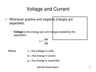
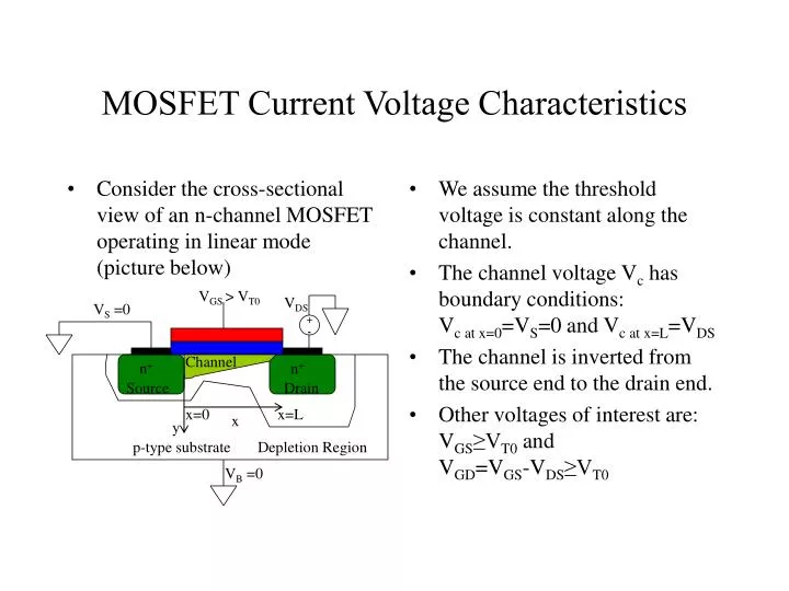
Consider the cross-sectional view of an n-channel MOSFET operating in linear mode (picture below). We assume the threshold voltage is constant along the channel. The channel voltage V c has boundary conditions: V c at x=0 =V S =0 and V c at x=L =V DS

E N D
Consider the cross-sectional view of an n-channel MOSFET operating in linear mode (picture below) We assume the threshold voltage is constant along the channel. The channel voltage Vc has boundary conditions: Vc at x=0=VS=0 and Vc at x=L=VDS The channel is inverted from the source end to the drain end. Other voltages of interest are: VGS≥VT0 and VGD=VGS-VDS≥VT0 MOSFET Current Voltage Characteristics VGS > VT0 VDS VS =0 + - Channel n+ n+ Source Drain x=0 x=L x y p-type substrate Depletion Region VB =0
The channel current (drain current ID) is caused by electrons in the channel region traveling from source to drain under the influence of the lateral electric field. If the total mobile electron charge in the surface inversion layer is assigned the vaiable QI(x), we can thus express this charge as a function of the gate-to-source voltage VGS and the channel voltage Vc(x) QI(x)=-Cox[VGS-Vc(x)-VT0] The thickness of the inversion layer tapers along the channel from the source towards the drain because the influence of Vgate-tochannel decreases from source to drain. If we consider a small incremental resistance dR for a differential segment of the channel assuming constant electron mobility mn at the surface we have: MOSFET Voltage Characteristics
The variable W represents the channel width. The electron surface mobility mn depends on the doping concentration of the channel region. We further assume that the channel current density is uniform across the segment where we are measuring the incremental resistance. ID flows between the source and drain. Applying Ohm’s law for this segment yields the voltage drop along the incremental segment dx: The above equation can now be integrated along the channel from x=0 to x=L using the boundary conditions for Vc We get: MOSFET Voltage Current Characteristic
Assuming that the channel voltage Vc is the only variable that depends on position x, the drain current is determined to be: This equation shows the dependence of the drain current on the process parameters such as oxide capacitance, carrier mobility, and bulk to source voltage. The drain current ID also depends on the device’s channel length and width. MOSFET Voltage Current Characteristics
MOSFET Voltage Current Characteristics • The equations: represent a simple view of the MOS transistor DC Voltage current equations. • There are models that better calculate the MOS transistor’s operation with accuracy.