Download

1 / 23
230 likes | 333 Views
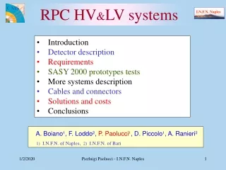
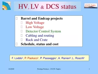
Investigated solutions and market survey for the HV-LV sub-systems. LV-HV Sub-systems CAEN solution : Resulting detector segmentation. MCM4. MCM1. MCM2. MCM6. MCM7. MCM3. MCM9. MCM10. MCM11. MCM12. MCM5. MCM8. ADC4. ADC3. ADC2. ADC1. FEE. FEE. FEE. FEE 1. FEE 2. FEE 4.

E N D
Investigated solutions and market survey for the HV-LV sub-systems g.de cataldo-A. Franco INFN bari
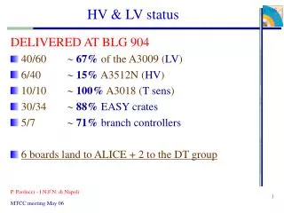
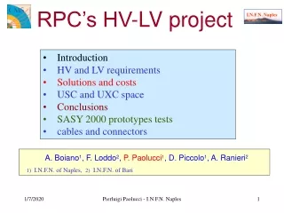
LV-HV Sub-systemsCAEN solution:Resulting detector segmentation MCM4 MCM1 MCM2 MCM6 MCM7 MCM3 MCM9 MCM10 MCM11 MCM12 MCM5 MCM8 ADC4 ADC3 ADC2 ADC1 FEE FEE FEE FEE 1 FEE 2 FEE 4 FEE 5 FEE 7 FEE 8 3 6 9 H6 H3 H9 H5 H4 H8 H1 H7 H2 12 MCM Segments 4 ADC Segment 9 FEE Segments, 180 (120) GASSIPLEX each 9 HV Segments, 36 (24) wires each, this requires a grouping of 12 sense wires Power requirements/segment V A W FEE+ +2.8 4.8 (3.2) 13.5 (9.0) FEE- -2.8 5.0 (3.4) 14.0 (9.5) ADC+ +5 2.0 10.0 ADC- -5 2.0 10.0 MCM +5 3.0 15.0 7 x HMPID MODULE 3 x CAEN SY1527(TCP/IP protocol) Boards: 9 x A1517 3V-6A(prot. by the end of 6/2001) 11 x A1518 5V-3.6A(.. by the end of6/2001) 6 x A1821A 3kV(Delivered and test under way) g.de cataldo-A. Franco INFN bari
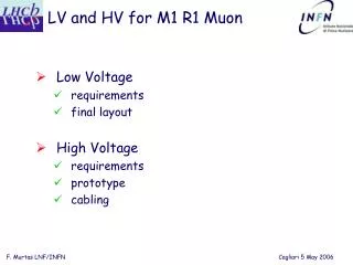
Layout of the CAEN solution Rear view Front view g.de cataldo-A. Franco INFN bari
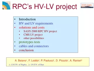
2 MCM Segments 1 ADC Segment 6 FEE Segments, 480 GASS. each 6 HV Segments, 48 wires each MCM1 MCM2 ADC1a ADC1b FEE 6 FEE 4 FEE 3 FEE 1 FEE 5 FEE 2 H3 H4 H1 H2 H6 H5 LV-HV Sub-systemsWIENER or EUTRON based solution: assumed detector segmentation Power requirements for each segment V A W FEE+ +2.8 5.9 17.8 FEE- -2.8 6.8. 18.7 ADCa+b +5 8.0 40.0 ADCa+b -5 8.0 40.0 MCM +5 18.0 90.0 For both these solutions, the HV PS is still based on the CAEN SY1527 g.de cataldo-A. Franco INFN bari
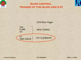
The Master Power Box can operate via • RS232 up 8 slave crates • CANbus up to 127 crate • TCP/IP offers performance for larger numbers of channels. FEE : 42 segments x 2 polarity 84 modules (2.8Vx12.7A=36.5W) MCM : 14 segment 14 modules (+5Vx18A=90W) ADC : 7 segments x 2 polarity 14 modules ( 5Vx16A=80W) Layout of the WIENER LV units Master Power Box Master power 3U box: Max DC Power/box =2.5 KW Up to 12 PL600 modules/box One module consist of one floating ch. 2..7V - 25A max 175W g.de cataldo-A. Franco INFN bari
EUTRON PS Units 3 x EUTRON BVD 720S 0..8 v 25 A 1 x EUTRON BVD 1500S 0..8 v 50 A PLC SIEMENS S7300 Connecting and sensing Board TO HMPID MODULES Layout of EUTRON-PLC devices For the EUTRON solution the power switching and sensing of each LV channel are based on a Siemens PLC system (relays and ADC modules) and a custom sensing board. This solution requires a control program developed ad hoc by the user. g.de cataldo-A. Franco INFN bari
First cost estimation(cables and connectors not included) • CAEN HV-LV • EUTRON LV + CAEN HV (PLC software development not included) • WIENER+ CAEN HV LV HV € CHF € CHF 111.350 172.500 23.150 36.000 66.200 102.500 30.100 46.700 56.800 88.000 30.100 46.700 g.de cataldo-A. Franco INFN bari
The EUTRON-PLC Control System • Requirements list; • The control system as a Finite State Machine; (bubble chart) • Apparatus layout and technical specifications of the sensing board; • the PLC readout software. g.de cataldo-A. Franco INFN bari E. Carrone,
The Requirements list It is intended to specify all the procedures to operate properly the LV power supply units while connected to the FE electronics. An incomplete example could be: • FEE LV switching ON: since the FEE requires ±2.8 V then both these polarities must be supplied contemporary, • FEE LV switching OFF: before a FEE segments is switched OFF, the facing HV segment (see St.Rep3 at http://richpc2.ba.infn.it) must be switched OFF. This sequence is mandatory to prevent FEE breakdowns due to charge accumulation on the MWPC cathode pads. (In fact the ground reference to the MWPC sense wires is ensured trough the FE electronics, then the low voltage at the corresponding FE electronics segment must be applied before the HV segment is switched ON); • Current and voltage ranges: Vload Iload must be in the admissible range: Vmin < Vload < Vmax, Imin < Iload < Imax. If Iload > Imax then the corresponding HV-LV segments must be automatically switched OFF according to FEE LV switching OFF sequence • Alarms handling … • … g.de cataldo-A. Franco INFN bari E. Carrone,
The control system as a Finite State Machine: state definition Taking into account the requirement list and how to properly operates the EUTRON units, the following “states” have been defined: • OFF ( P.S. in Standby, relays OFF and Vout=0) • Calibration (reading Voutput from units) • Configuration (FEE segment selection) • Standby (LV system in STBY status) • ON (Ready For Physics: P.S. STBY removed, check ofCurrent/Voltage values) g.de cataldo-A. Franco INFN bari E. Carrone,
Alarm Condition COMMANDS COMMANDS START START CALIBRATE RUN START CONFIGURE FILL CONFIGURE STOP PURGE SUSPEND STOP FEED MAN CONF RESET RESET STOP STBY CAL SUSPEND FEED CALIBRATE STATES OFF CALibration ON ALARM OFF CONFiguration RESET STBY Standby ON Ready ALARM LV C.S. representation When the ON state is active Iload and Vload are monitored on all the active FEE segments. If one of these values is out of range then the relevant FEE segment is switched OFF and the HV system is contemporary notified to switch OFF the corresponding HV segment. During the transition ON->STBY the HV status must be checked and if it is HV-ON then the LV C.S. must kill the HV system. STATES OFF Stop Running Filling Ready LV: the bubble chart representation g.de cataldo-A. Franco INFN bari E. Carrone,
Power Supply Dummy resistive Load NT Workstation CH1/2 Power line Sensing Board Set and reading PS Vout Vload sensing line Ethernet Iload sensing line from-to PLC relays Siemens S300 PLC Apparatus Layout In order to split the PS current into several channels, each one connected to one FFE segment, a PLC relays module is used. The Vload-Iload measurement is based on a sensing board read out via 8CH ADC module. Power Supply: EUTRON BVD720S, 0-8V, 0-25 A. PLC: Siemens S300 Analog Inputs 8 x 12 bit. g.de cataldo-A. Franco INFN bari E. Carrone,
Vs - Vs + Sensing Board g.de cataldo-A. Franco INFN bari E. Carrone,
Signal Conditioning The input stage of the ADC accepts the max Common Mode Voltage UCM= 2.5V. This imposes a Vsensing attenuation via a resistive net (UCM= (Vin+Vo)/2 3.9 V) . THE NET RESISTOR æ ö æ ö R 2 R 4 R 4 = - = - + ç ÷ ç ÷ V V V V V + + - + sr s s in sen sin g + + + R 1 R 2 R 3 R 4 R 3 R 4 è ø è ø + ( ) R 4 R 3 R 4 = + Þ = - V V V V V V + + sr ped sen sin g sen sin g sr ped + R 3 R 4 R 4 In order to measure the Vped, Rsens has been put in short circuit (Vsensing=0) and this resulted in Vped=5 mV. To evaluate the Ucm attenuation factor A= R4/(R3+R4), Vsr and Vsensing have been measured and it resulted in A=0.1325: Vsensing = (Vsr - Vped)/A Finally Iload = Vsensing / Rsens With the ADC LSB of 22.4 mV in the range +-80mV, a current sensitivity d=LSB/A*Rs= 2.8 mA on the Iload is achieved. This allows the C.S. to detect the single FEE chip failure which drains 45 mA per polarity. g.de cataldo-A. Franco INFN bari E. Carrone,
Process Input Word ADC “brute” value PIW 288 “V sensing + ADC” --- DEC 8872 PIW 290 “V sensing – ADC” --- DEC -14440 PIW 292 “V load + ADC” --- DEC 15496 PIW 294 “V load – ADC” --- DEC -15496 MD 100 "I load +“ --- REAL 3.737275 MD 108 "I load -“ --- REAL -4.101968 MD 132 "V load +“ --- REAL 2.802372 MD 124 "V load -“ --- REAL -2.802372 MD 20 "V sensing + input ADC“ --- REAL 25.67129 MD 28 "V sensing - input ADC“ --- REAL -41.7824 [V] [A] Memory Double Word [mV] PLC VAT (Variable Table) g.de cataldo-A. Franco INFN bari E. Carrone,
PLC Instruction List NETWORK TITLE =Sensing Current CH + AN Q 4.1; S Q 4.1; AN Q 4.2; S Q 4.2; AN Q 4.0; S Q 4.0; AN Q 4.3; S Q 4.3; L PIW 288; ITD ; DTR ; L 2.893518e-003; *R ; T “V sensing + input ADC"; L 5.000000e+000; L “V sensing + input ADC"; +R ; T MD 68; L MD 68; L 7.566840e+000; *R ; T MD 84; L MD 84; L 6.210000e+001; /R ; T "I load +"; Relays switches ADC reading value [mV] Integer: 16 bit 32 bit Pedestal offset Integer 32 bit IEEE-FP 32 bit 1/A where A=attenuation factor V I Conversion g.de cataldo-A. Franco INFN bari E. Carrone,
Control System for the CAEN SY1527 in the PVSS environment. The Configuration Program A devoted program reads from a file the HV sub-system configuration ( # HMPID modules, HVsegment/module) and creates the DataPoint data base in the PVSS environment. These data points are automatically created according to the specified variables (Crate/Board/Channel) of the CAEN OPC Server and it sets a link between the OPC variable addresses and the PVSS data base. g.de cataldo-A. Franco INFN bari
Monitoring panel of the HMPID HV System Alarm condition Link to the Monitoring Panel of SY1527 Link to the Monitoring Panel of the HV segment Segment disabled “Burned-out” Segment Link to the Enable/Disable Panel Link to the Channel Configure Panel g.de cataldo-A. Franco INFN bari
Monitoring panel of the HV Segment (when the CAEN SY1527 OPC serv. Is running!) Channel settings Channel Status HV-ON Channel Name Actual value of Parameters Trend display settings Trend parameter Chart g.de cataldo-A. Franco INFN bari
Enabling/disabling HV Segments Option for global Enable/Disable action Segment Enabled Segment Disabled Exit g.de cataldo-A. Franco INFN bari
HV Channel configuration Parameter Value Parameter Name Cancel all the changes Save the present configuration Exit g.de cataldo-A. Franco INFN bari
SY1527 Control panel Inserted board status Board description Power System Name Empty slot Crate Alarm condition Crate Front panel status Fan & Power unit Status Crate commands Crate settings g.de cataldo-A. Franco INFN bari
HMPID DCS: LV prototype panel g.de cataldo-A. Franco INFN bari