Download
1 / 11
110 likes | 122 Views
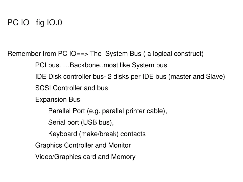
PC IO fig IO.0. Remember from PC IO==> The System Bus ( a logical construct) PCI bus. …Backbone..most like System bus IDE Disk controller bus- 2 disks per IDE bus (master and Slave) SCSI Controller and bus Expansion Bus

E N D
PC IO fig IO.0 • Remember from PC IO==> The System Bus ( a logical construct) • PCI bus. …Backbone..most like System bus • IDE Disk controller bus- 2 disks per IDE bus (master and Slave) • SCSI Controller and bus • Expansion Bus • Parallel Port (e.g. parallel printer cable), • Serial port (USB bus), • Keyboard (make/break) contacts • Graphics Controller and Monitor • Video/Graphics card and Memory
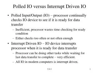
IO_Variations • - Control Unit and Buffer • A Read = Dev -> Buffer -> Memory • A Write = Memory -> Buffer -> Dev • - 2 IO Interrupts per IO • - Match device speed to Bus speed • Minimize Buffer utilization • - Direct Memory Access (DMA) – off-load data move from CPU
IO_Variations - Mainframe (fig IO.1 360 IO) Many System Buses …now called “Channels” Multiple Control Units on each Channel Almost all Control Units (CU’s) are buffered… not originally- but speed mismatch became a problem Byte-Multiplexor, Selector, and then Block-Multiplexor Control Unit can connect to multiple Channels (fig IO.2) Control unit can connect to different channels on different CPUs Channel to Channel connections possible if close Channel Programs allow many complex operations without an IO Interrupt (covered later)
Mainframe IO • Basic Addressing Structure • SIO instruction Specifies “device address” • Device address defines path to device • Today IO subsystem determines “path” to device • Minimizes bottlenecks to device • Supports higher availability in case of failures (Channels, CUs.) • Provides image of “floating” channels • Cost- longer time to initiate an IO • TPF doesn’t use it • Some IO Instructions (e.g. SIOF) release processor “early”
Mainframe IO • Notion of a sub-channel i.e. uuu a.k.a. UCW • Contains information about an IO operation to a device • e.g. CCW address, current state • Contains current path to device from processor
Mainframe IO - CCW Format0 (64 bits..8 bytes) – (fig IO.4) Command Code, Data address(24 bits), Flags, spare, Byte Count Flags CD – data chain CC – command chain SLI – suppress length indication (e.g. read a terminal line) SKIP – skip data transfer PCI - program control interrupt IDA - data address points to first IDAW word (fig IO.5) MIDA -data address points to first MIDAW
Mainframe IO • -CCW Format1 (64 bits..8 bytes) (fig IO 6a) • Command Code, Flags, Byte Count, Data address(31 bits) • Flags • CD – data chain • CC – command chain • SLI – suppress length indication (e.g. read a terminal line) • SKIP – skip data transfer • PCI - program control interrupt • IDA - data address points to first IDAW word (fig IO.5) • SUSPEND – suspend program ..before this command • MIDA -data address points to first MIDAW (fig IO.6 a,b) -
Mainframe IO • IDAW and MIDAW formats IDAW1 - 0|| 31 bit address IDAW2 - 64 bit address MIDAW – first 5 byres reserved flags bytecount 64 bit address • Flags Last MIDAW in program Skip Data Transfer interrupt
Mainframe IO - A
Mainframe IO - A
Mainframe IO - A