Download
1 / 3
40 likes | 57 Views
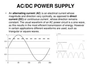
Oscillator circuit is one that converts DC power into AC power at a frequency without any input signal. Oscillators are commonly used in communication systems to generate carrier frequency ranging from audio frequency 20 Hz to radio frequency 100G Hz . There are two main classes of oscillators, harmonic oscillator with sinusoidal output e.g. sine wave and relaxation oscillator with non sinusoidal output e.g. square wave, triangle wave, etc. . In this paper, class A Colpitts oscillator with LC feedback circuit is designed as a radio frequency oscillator to generate the output signals at 5M Hz. After designing, this circuit is simulated with Multisim software to analyze the effect of power supply on its frequency stability. Three supply voltages, 14 V, 12 V and 10 V are set as sample parameters to analyze the variation of frequency and voltage of the output signal. Changing DC power supply one by one as the above selected parameters in Multisim, the change of value of frequencies are noted and output signal results are also shown with the help of virtual oscillator. Thit Waso Khine "Designing Class a Colpitts Oscillator and Analyzing the Effect of DC Power Supply on its Frequency Stability" Published in International Journal of Trend in Scientific Research and Development (ijtsrd), ISSN: 2456-6470, Volume-3 | Issue-5 , August 2019, URL: https://www.ijtsrd.com/papers/ijtsrd28022.pdf Paper URL: https://www.ijtsrd.com/engineering/electronics-and-communication-engineering/28022/designing-class-a-colpitts-oscillator-and-analyzing-the-effect-of-dc-power-supply-on-its-frequency-stability/thit-waso-khine<br>

E N D
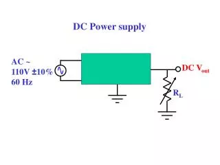
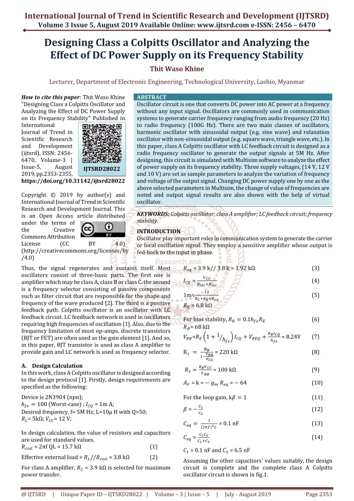
International Journal of Trend in Scientific Research and Development (IJTSRD) Volume 3 Issue 5, August 2019 Available Online: www.ijtsrd.com e-ISSN: 2456 – 6470 Designing Class a Colpitts Oscillator and Analyzing the Effect of DC Power Supply on its Frequency Stability Thit Waso Khine Lecturer, Department of Electronic Engineering, Technological University, Lashio, Myanmar How to cite this paper: Thit Waso Khine "Designing Class a Colpitts Oscillator and Analyzing the Effect of DC Power Supply on its Frequency Stability" Published in International Journal of Trend in Scientific Research and Development (ijtsrd), ISSN: 2456- 6470, Volume-3 | Issue-5, August 2019, pp.2353-2355, https://doi.org/10.31142/ijtsrd28022 Copyright © 2019 by author(s) and International Journal of Trend in Scientific Research and Development Journal. This is an Open Access article distributed under the terms of the Creative Commons Attribution License (CC (http://creativecommons.org/licenses/by /4.0) Thus, the signal regenerates and sustains itself. Most oscillators consist of three-basic parts. The first one is amplifier which may be class A, class B or class C. the second is a frequency selector consisting of passive components such as filter circuit that are responsible for the shape and frequency of the wave produced [2]. The third is a positive feedback path. Colpitts oscillator is an oscillator with LC feedback circuit. LC feedback network is used in oscillators requiring high frequencies of oscillation [1]. Also, due to the frequency limitation of most op-amps, discrete transistors (BJT or FET) are often used as the gain element [1]. And so, in this paper, BJT transistor is used as class A amplifier to provide gain and LC network is used as frequency selector. A.Design Calculation In this work, class A Colpitts oscillator is designed according to the design protocol [1]. Firstly, design requirements are specified as the following: Device is 2N3904 (npn); ℎ??= 100 (Worst-case) ; ??? = 1m A; Desired frequency, f= 5M Hz; L=10µ H with Q=50; ??= 5kΩ; ???= 12 V; In design calculation, the value of resistors and capacitors are used for standard values. ????? = 2πf QL = 15.7 kΩ Effective external load = ??//????? = 3.8 kΩ For class A amplifier, ?? = 3.9 kΩ is selected for maximum power transfer. ABSTRACT Oscillator circuit is one that converts DC power into AC power at a frequency without any input signal. Oscillators are commonly used in communication systems to generate carrier frequency ranging from audio frequency (20 Hz) to radio frequency (100G Hz). There are two main classes of oscillators, harmonic oscillator with sinusoidal output (e.g. sine wave) and relaxation oscillator with non-sinusoidal output (e.g. square wave, triangle wave, etc.). In this paper, class A Colpitts oscillator with LC feedback circuit is designed as a radio frequency oscillator to generate the output signals at 5M Hz. After designing, this circuit is simulated with Multisim software to analyze the effect of power supply on its frequency stability. Three supply voltages, (14 V, 12 V and 10 V) are set as sample parameters to analyze the variation of frequency and voltage of the output signal. Changing DC power supply one by one as the above selected parameters in Multisim, the change of value of frequencies are noted and output signal results are also shown with the help of virtual oscillator. KEYWORDS: Colpitts oscillator; class A amplifier; LC feedback circuit; frequency stability. INTRODUCTION Oscillator play important roles in communication system to generate the carrier or local oscillation signal. They employ a sensitive amplifier whose output is fed-back to the input in phase. IJTSRD28022 BY 4.0) ??? = 3.9 k// 3.8 k = 1.92 kΩ ??? = (3) ??? ????????? (4) 1m= ?? ????????? ?? = 6.8 kΩ For bias stability, ??= 0.1ℎ???? ??= 68 kΩ ???=???1 +1ℎ?? ? R? = ????? ??? ??= (5) (6) ????? ???= 8.24V (7) ????+ ????+ ?? = 220 kΩ (8) ????? ??? = 100 kΩ ?? = k = −????? = − 64 For the loop gain, k? = 1 ? = −?? (9) (10) (11) ?? (12) ???= ? (???)?? = 0.1 nF (13) ??? = ???? ????? (14) ?? = 0.1 nF and ?? = 6.5 nF Assuming the other capacitors' values suitably, the design circuit is complete and the complete class A Colpitts oscillator circuit is shown in fig.1. (1) (2) @ IJTSRD | Unique Paper ID – IJTSRD28022 | Volume – 3 | Issue – 5 | July - August 2019 Page 2353
International Journal of Trend in Scientific Research and Development (IJTSRD) International Journal of Trend in Scientific Research and Development (IJTSRD) @ www.ijtsrd.com www.ijtsrd.com eISSN: 2456-6470 Similarity, the output signal result at Vcc = 10 V is also shown in fig. 3 and it is found that the value of frequency is more than the value at Vcc = 12 V but peak to peak voltage is Similarity, the output signal result at Vcc = 10 V is also shown in fig. 3 and it is found that the value of frequency is more than the value at Vcc = 12 V but peak to peak voltage is less than above. Fig.1 Class A Colpitts oscillator circuit Fig.1 Class A Colpitts oscillator circuit B.Simulation Results All oscillators take time to start. In this simulation, the difference time taken to start oscillates and frequency values at the selected parameters of DC power supply are shown. Firstly, the output signal results of oscillator at Vcc = 12 V is shown in fig. 2. All oscillators take time to start. In this simulation, the difference time taken to start oscillates and frequency values at the selected parameters of DC power supply are shown. Firstly, the output signal results of oscillator at Vcc = 12 V is Fig. 3 Output signal (frequency = 4.66 MHz) Fig. 3 Output signal (frequency = 4.66 MHz) Finally, the last output signal result at Vcc = 14 V is shown in fig. 4.There is observed that the frequency value is the least among them and the time taken is also the least. Finally, the last output signal result at Vcc = 14 V is shown in fig. 4.There is observed that the frequency value is the least among them and the time taken is also the least. Fig. 2 Output signal (frequency = 4.26 MHz) Fig. 2 Output signal (frequency = 4.26 MHz) @ IJTSRD | Unique Paper ID – IJTSRD2 28022 | Volume – 3 | Issue – 5 | July - August 2019 August 2019 Page 2354
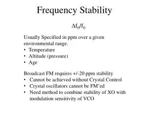
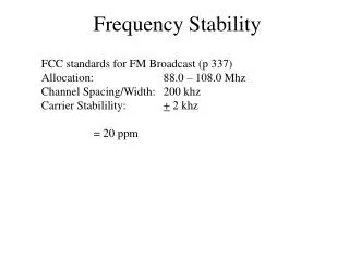
International Journal of Trend in Scientific Research and Development (IJTSRD) @ www.ijtsrd.com eISSN: 2456-6470 C.Analysis of the Simulation Results Frequency stability is one of the characteristics of an oscillator and it varies with varying power supply. Depending on these power supplies the value of time taken to start is varied. In this oscillator design, time taken is generally calculated as t = ? the above data, the analysis values are summarized in the table as the following. TABLE I. Difference of values at selected Vcc(s) Frequency (MHz) Vcc (10 V) ≈4.66 Vcc (12 V) ≈4.26 Vcc (14 V) ≈4.11 D.Conclusion From the simulation results, the proposed class A Colpitts oscillator (5 MHz) is designed successfully and the effect of power supply on frequency stability is analyzed. Frequency stability is one of the important facts for oscillators and it is affected by temperature changes, mechanical vibrations and power supply and there is also left for analysis of the other two factors in this paper. Acknowledgment Firstly, the author would like to thank her beloved parents and her husband for their supports and encouragements to do this paper. The author also wishes to give her thanks to all teachers who teach her in her whole life. References [1]Glifford D.Ferris, "Elements of Electronic Design" Minneapoils/St.Paul.NewYork.Los Francisco, 1995. ?× ? and is nearly 10 µs. From Time taken ( ≈ ??µ?) > 10µ? ≈ 10µ? < 10µ? pk- pk (V) ≈1.8 ≈2.5 ≈2.6 Angeles. San [2]Electronic Devices; Conventional Current Version (Ninth Edition). Thomas L. Floyd (2011). [3]Steven T. Karris,"Electronic Device and Amplifier Circuits, (Third Edition). [4]Haykin Simon, Communication Systems, John Wiley, 4th Edition, 2001. Fig. 4 Output signal (frequency = 4.11 MHz) @ IJTSRD | Unique Paper ID – IJTSRD28022 | Volume – 3 | Issue – 5 | July - August 2019 Page 2355