Download
1 / 17
170 likes | 330 Views
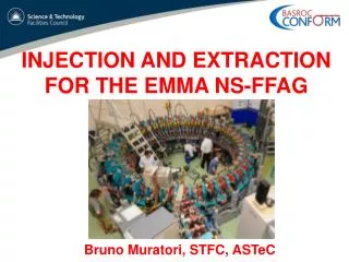
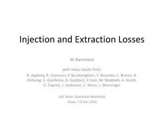
SNS Injection and Extraction Systems Issues and Solutions by M. Plum for the SNS team and our BNL collaborators HB2008 Nashville, TN Aug. 24-29, 2008. 150 kW Injection dump. Quadrupole magnet and dual-plane dipole corrector. Ring injection area. Ring. Injection dump beam line.

E N D
SNS Injection and Extraction Systems Issues and Solutions by M. Plum for the SNS team and our BNL collaborators HB2008Nashville, TNAug. 24-29, 2008
150 kW Injection dump Quadrupole magnet and dual-plane dipole corrector Ring injection area Ring Injection dump beam line Injection painting kicker magnets Gradient septum Secondary foil 4 magnet chicane Primary foil Injection painting kicker magnets HEBT beam line Injection septum SNS injection M. Plum, HB2008 Workshop
Functions of chicane magnets • Closed orbit bump of about 100 mm • Merge H- and circulating beams with zero relative angle • Place foil in 2.5 kG field and keep chicane #3 peak field <2.4 kG for H0 excited states • Field tilt [arctan(By/Bz)] >65 mrad to keep electrons off foil • Funnel stripped electrons down to electron catcher • Direct H− and H0 waste beams to IDmp beam line M. Plum, HB2008 Workshop
SNS injection issues • Chicane magnets do not function as designed • Bend angles have been adjusted to give good injection into ring, but this causes problems in the injection dump beam line • Original design did not allow individual control over the H0 and H− waste beams • We’ve since added a C-magnet just downstream of the septum magnet • High beam loss in injection dump beam line • Beam halo • Scattering in the secondary stripper foil • Beam profile and position info at the vacuum window / dump difficult to determine • We plan to add a view screen at the vacuum window M. Plum, HB2008 Workshop
Inj. dump beam line modifications to date Radiation monitor on vacuum window water cooling return pipe New C-magnet Increase septum magnet gap by 2 cm Oversize & thicker primary stripper foil New WS, view screen,BPM, NCD (ridicules) Thinner, widersecondary stripper foil Shift 8 cm beam left Electron catcher IR video beam line drawing from J. Error M. Plum, HB2008 Workshop
Beam loss due to scattering • For a given aperture, the probability of Rutherford (large angle Coulomb) scattering outside the aperture separately depends on the target and the apertures • By replacing the secondary foil with a thicker material we can estimate the fraction of the loss due to scattering (R. Macek, 2004) angles target (Plots from J. Holmes) ratio Number exceeding angle Number exceeding angle Foil total Ratio VS Foil Scattering angle (mrad) Scattering angle (mrad) M. Plum, HB2008 Workshop
Single beam species tuned to minimize beam loss Simulated H0 beam, production tune One well-tuned beam ratio VS ratio VS foil x10 foil x10 Foil: (total loss) = a x (scattering) + b x (base loss) View screen: (total loss) = 50 x a x (scattering) + b x (base loss) Conclude that for simulated H0 beam, 30 to 90% of beam loss is due to foil scattering. We need a thinner foil! We expect similar numbers for production case with both H− and H0 waste beams M. Plum, HB2008 Workshop
Foil scattering losses with thinner sec. foil One well-tuned beam – old foil One well-tuned beam – new foil ratio ratio VS VS foil x10 foil x100 Replaced secondary stripper foil August 2008 Old foil 18 mg/cm2 carbon-carbon (Allcomp) New foil 3.2 mg/cm2 polycrystalline graphite (ACF Metals) Ratio of losses view screen / foil increased from 50 to 300 Conclude that beam loss due to scattering is now ~6x less M. Plum, HB2008 Workshop
HB2008 injection Q&A • Does the system perform as expected? Did the simulations/calculations performed during the design stage accurately predict the actual performance? • No. Design bend angles of chicane set points were not correct. Beam loss in injection dump beam line was much higher than expected. Vertical deflection in chicane #4 was not expected. • What are the major limitations in performance? Were they known in the design stage? • Beam loss in the injection dump beam line. Not known in the design stage. • If someone were to begin now designing the same type of system for a similar machine, what is the one piece of advice that you would give them? • 3-D field simulations and tracking in complex regions such as injection area. Map magnets well enough to determine higher order multipoles, for a wide range of currents. Allow independent control over multiple beams. M. Plum, HB2008 Workshop
Extraction kickers Lambertson septum magnet RTBT beam line Ring extraction M. Plum, HB2008 Workshop
Extraction system issues • Tilted beam (cross plane coupling) • Due to large skew quad component in the extraction septum magnet • Lack of diagnostics to measure beam path in ring and first 27 m of the RTBT • Have not yet found set points that give a good launch into the RTBT • Lack of beam profile and position info at the vacuum window and target • Diagnostic closest to target is 9.5 m away • Still have a discrepancy between halo thermocouple monitor and the BPM extrapolation method M. Plum, HB2008 Workshop
Tilted beam caused by skew quad component in extraction septum magnet vertical horizontal (S. Cousineau) Tilted beam on the target view screen RTBT20 wire scanner for 3 different horizontal injection kicker amplitudes X (mm) Beam distribution at BPM25 in the extraction line, reconstructed using single minipulse injection and varying extraction time (S. Cousineau & T. Pelaia) Y (mm) M. Plum, HB2008 Workshop
Harmonics calculation (see J.G. Wang HB2008 poster) ~5% due to proximity of quad ~75% due end effects Integrated skew quad component 0.26 – 0.28 T at 1 GeV beam energy M. Plum, HB2008 Workshop
End of RTBT BPM Wire scanner or harp Wire scanners Harp Thermocouple halo monitor 9.52 m from last BPM & profile monitor to face of target M. Plum, HB2008 Workshop
How we determine position and profile at the target • Thermocouple halo monitor used to center beam on target • Physics application “RTBT Wizard” • Determines beam position based on upstream beam position monitors – ~4 - 8 mm different than halo monitor • Determines beam density and rms beam size based on on-line model and fitted profiles S. Cousineau and T. Pelaia M. Plum, HB2008 Workshop
HB2008 extraction Q&A • Does the system perform as expected? Did the simulations/calculations performed during the design stage accurately predict the actual performance? • Except for cross plane coupling, as near as we can tell, it is working as expected. We knew there were not as many diagnostics as we’d like. • What are the major limitations in performance? Were they known in the design stage? • Difficult to determine extraction kicker set points due to lack of beam position information. Difficult to determine beam size, density, and position on target. We knew this in the design stage. • If someone were to begin now designing the same type of system for a similar machine, what is the one piece of advice that you would give them? • Map magnets well enough to determine higher order multipoles, and take into account field distortion due to nearby magnets. Especially important for large beams. • Install adequate diagnostics to allow easy determination of critical beam parameters M. Plum, HB2008 Workshop
Summary & future work • SNS injection issues are fairly well understood • Beam loss is still too high • We are working on a view screen for the injection dump • We are now considering another increase in the aperture of the injection dump beam line • SNS extraction issues are well understood • We are working to modify the extraction septum magnet to reduce skew quad component • We are working on a view screen for the target M. Plum, HB2008 Workshop