Download
1 / 32
320 likes | 323 Views
Mucool Test Area Instrumentation. University of Illinois (UIUC) Debbie Errede, Mike Haney, Zack Conway Fermilab Mike Shea University of Chicago Kara Hoffman, Mark Oreglia MUTAC @FNAL Speaker: Debbie Errede Jan 14, 2003. University of Illinois Responsibilities.

E N D
Mucool Test Area Instrumentation University of Illinois (UIUC) Debbie Errede, Mike Haney, Zack Conway Fermilab Mike Shea University of Chicago Kara Hoffman, Mark Oreglia MUTAC @FNAL Speaker: Debbie Errede Jan 14, 2003
University of Illinois Responsibilities • List of signals for Mucool Test Area • Instrumentation of Absorber - Includes some instrumentation research and development - Implementation of definitions of safety (see D. Allspach) for our use in this area. Decision to pass both Fermilab and European safety standards for test area…with MICE in mind. • Signals from all cooling channel components to our rack and to Fermilab IRMs (internet rack monitors) for ACNET access.
Other Instrumentation Projects • Bolometry for Beam Profile- University of Chicago: Kara Hoffman and Mark Oreglia • Fast Timing Cerenkov Detector - Fermilab: Alan Bross (unfunded to date) • Magnet and RF CavityInstrumentation - LBL, Fermilab,…: Mike Green, Al Moretti
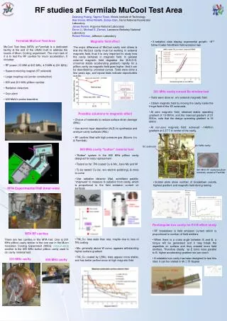
Nickel Carbon 0.8 V 0.8 V 10 ms 20 ms Thin film bolometry for beam profiling Bolometers detect radiation when it induces a rise in temperature in materials whose resistivity is temperature dependent. We have proof of principle for several materials for a photon beam (Xe flashlamp, YAG laser). cryostat
Beamtests We’ve performed beam tests at Argonne with a 20 MeV electron beam. We are working to evaluate the results and study sources of background present in beam conditions.
University of Illinois:List of Signals in MTA • Beam Line (Carol Johnstone) • Beam Properties Measurements (CJ) • Cryogenics (Barry Norris) • A. H2 • B. He • Experiment • A. Absorbers (Mary Anne Cummings, Edgar Black) • B. RF Cavities (Al Moretti) • C. Solenoid (Al Moretti, M. Green)
Cryogenics # signals # signals Beam Line Elements • Helium • inlet temp (carbon) 1 • outlet temp (carbon) 1 • inlet temp (platinum) 1 • outlet temp (platinum) 1 • inlet pressure 1 • outlet pressure 1 • He level 2 • N2 level 1 • solenoid coil temperature 4 (platinum) • 750 KeV Chopper 1 • dipole magnets currents 5 • quad magnet currents 13 • stripping foil 1 • collimater positions - 2 units 8 • ion chamber 1 (in front of beam dump) • Temperature for quads and dipoles 18 Beam Properties Measurements • Tune Parameters ? data set • Beam Position Monitors 20-40 • Toroid Beam Current Monitor 1 (slow response) • Fast Beam Current Monitor 1 (fast response) • Beam Loss Monitors 5-10
inlet temp(C) 1 outlet temp(C) 1 inlet temp (Pt) 1 outlet temp (Pt) 1 temperature, other 6 inlet pressure 1 outlet pressure 1 pump delta pressure 1 H2 supply pressure 1 H2 vent pressure 1 H2 vent pipe pressure 1 cryo vacuum pressure 2 pump voltage 1 pump current 1 pump speed 1 pump status (run/not) 1 heater voltage 1 heater current 1 heater power 1 beam permit 1 hazardous gas 10 O2 deficiency hazard 8 Cryogenics Hydrogen # signals Experiment - RF, Solenoid (outside) • solenoid current 1 • rad level on chipmunks 10? • cavity forward power 1 • cavity reflected power 1 • cavity RF level(E-field?) 2 • cavity vacuum level 2 • timing channels 10? NON DATA • CCD camera image • microphone sound byte
Experiment – Absorber #signals • temperature 8 • pressure transducers (see under cryo) • laser occlusion sensor 4 • piezo vibration sensors 2 • strain gauges 2 • bolometry 25?? • O2 sensors 3 per each of 5 flanges 15 • O2 sensors on H2 exhaust line 10 • other channels ??
MTA InstrumentationData PathsUniversity of Illinois • Determining data sets and pathways from cooling channel components to readout. • Providing safe pathways to electronics , PC, and ACNET.
FISO 16 chan ADC Lakeshore IRM PC MTA Instrumentation :Data Paths: LabView Perspective To PC/LabView consumers From ACNET sources Strain, temp Slow, local signals(e.g. magnet current(s)) temp Fast, local signals(e.g. piezo transducer)
Instrumentation for Absorber : Safety • Seeking an intrinsically safe solution for instrumenting the LH2 absorber in the MTA • Prudent to accommodate MICEand European safety considerations Two solutions • Intrinsic safety, if possible • Limited power per channel • Good idea for Fermi; required for Europe • Gas-purged enclosure, if necessary • 19” rack, 40U tall
Two Possibilities (1) • Intrinsically safe Hazard Safe Sealed Conduit(s) Barrier(s) ACNET IRM Cryo(temp) FISO PC w/16 chan ADC network power Intrinsically safe signal conditioners and transmitters UPS
Two Possibilities (2) • Gas-purged box Hazard Safe Barrier(s) Sealed Conduit(s) ACNET IRM Cryo(temp) FISO PC w/16 chan ADC network power UPS
fuse Power + Signal “safe circuit” Return Ground Instrumentation Electronics Safety (basic) Barrier • MTL7055ac barriers • Low level AC • 24 W per line • 3 V max • MTL7060ac barriers • Star-connected AC • 101 W per line • 8.5 V max
Instrumentation for Absorber(currently being tested in Urbana) • FISO Fiber-optic strain and temperature • BUS chassis, with 4 (up to 8) modules • 1000 readings/s • RS-232 interface (to PC) • FOS-N strain sensors • +/- 5000 me; 0.01% full scale; 0.2mm O.D. • FOT-L temp sensors • 0.1 K resolution; 1.5mm x 32mm (10mm active) • Slow: 1.5 second response… • Lakeshore 218S • 8 channel cryo temperature monitor • +/- 21m K at 10 K • 16 readings/s • GPIB interface (to PC) • TG-120PL GaAlAs diodes (8) • -180mV/K at 4.2 K • B < 5 T; rad hard
Instrumentation Electronics for Absorber, etc. • Gateway E-4000 PC • 1.8 GHz, 1Gbyte RAM, 0.5Gbyte cache • 120Gbyte disk, Windows 2000 • 15” LCD flat panel display • 640x480 CCD camera, microphone • PCI-MIO-16E-1 • 16 channel ADC, 1.25 Msample/s, 12 bits, +/-10 V • Tripplite Smart UPS • 3000 VA
Instrumentation: Electronics for ACNET • IRM • 64 channel multiplexed ADC • 16 bit, 100 Ksamples/s • ACNET network connection • All PC data will be posted to IRM for ACNET access
Signals inside the cryostat • Piezo vibration sensor • via (16 chan/12 bit) ADC and LabView (PC) • Local (64 chan/16 bit) IRM channels • via “LabView” (see last slide) • other channels (?) • placeholder for the future… • 8 (cryo) temperatures • readout via GPIB + LabView (PC) • Multiple fibers • FISO strain, temperature (4) • Pressure, flow? • Laser occlusion (2) • Simple spark detectors (2) • (light pipe to photodiode) • 25(ish) 4-wire bolometry strips
Signals outside cryostat • USB (4 wires, and shield) for CCD camera and microphone • via PC • Many voltages, currents, temperatures, pressures • magnets, beam position monitors, etc. • Most available from ACNET or local IRM • via “LabView” (see last slide) • or Cyro-PLC
Illinois Grad Student Efforts (Zack Conway) LabView interface • GPIB to cryo temp monitor - works • PC-internal ADC (e.g. for piezo) – “works” • Simple ADC data read - works • High rate collection and compression – not yet • IRM communications • IRM-ADC Read - works • Write Integration – remains R&D of FISO temp/pres transducers - presently dipping temperature transducers into liq N and comparing with diode that is known to operate in this temperature region.
Illinois Grad Student Efforts(Zack Conway) FISO R&D • FISO strain and temp sensors • Not officially rated below -40 C (!) • Temp has been used at 35 K (custom) by others • No experience with strain gages • Company very willing to work with us • To adjust signal conditioner, correction curves, etc. • Will require some form of agreement • Yet freedom to use and publish measurement
Physics Lab 1 Setup(In Urbana) Left to right: Computer, FISO Bus system, and Lakeshore 218 temperature monitor
FISO Bus System • Using RS-232 to communicate with Bus system • 4 signal conditioners(room for 4 more) • Lakeshore 218 temperature Monitor • RS-232 & GPIB • 8 channel temperature monitor • Using GaAlAs diodes to monitor temperature
Internet Rack Monitor(IRM) • 64 A/D channels and 64 bits of D/A
Time schedule MTA(M. Popovic) • Fall ’03 - Beneficial occupancy ; get into building and start installing things. • + 6 mos.: (Winter 2004) to install experimental apparatus + cryo system + safety systems + liq H2 filling system + instrumentation • Choice: Fill w. something else besides liq H2. • Convection-style absorber: Japanese absorber ready to be tested • + 3 – 6 mos.: for filling and experimenting (2 absorbers) • deinstallation and installation : schedule inefficiency due to cryo/Tevatron we are running parasitically wrt cryo systems, Linac Operations and maintenance. • June ‘04 : Beam related hydrogen absorber test. • Sept ‘04: Short fully integrated Cooling Section: hydrogen absorbers, Be-window RF cavity, superconducting solenoid • Sept ’04: High power RF Test : Be-window RF cavity : Grid based RF cavity - both 200 MHz and805 MHz
AccomplishmentsIllinois • Hardware acquired • PC, FISO, Lakeshore (temp), IRM, etc. • All major items • Piecewise software written • IRM communications: to, from • Lakeshore readout • FISO readout • All major elements • Intrinsically safe solutions (barriers)
Current Plan Illinois • FISO qualification of temp/strain sensors at cryogenic temperatures • Full software integration • Of piecewise solutions, in hand • Cable plant into solenoid • Shielding, filtering, protection • both against noise, and surges
Open Issues Illinois • Wire+Shielding Concerns • Noise/sensitivity issues due to wire+barrier resistance? • Approx 12 W /ft for 36 AWG manganin wire • 48 W to 202 W added by barrier • And diode capacitance… • Common mode (surges) due to magnets? • Need to protect electronics without burning barriers for example during magnet quench. • Cable plant into solenoid
Summary • List of signals continues to be updated (UIUC) • Intrinsically safe solutions are being pursued. (UIUC+D. Allspach and larger cryo group ) • Illinois (UIUC) focuses on instrumentation of absorber and interface to ACNET/Fermilab - development of FISO transducers (white light optics) which are rad hard (Brookhaven test – H. Kirk) for use at low temperatures (liquid H, He, N) in conjunction with FISO company. • University of Chicago (K. Hoffman, M. Oreglia) continues to make progress on Bolometry efforts, including photon beam test results, with electron beam data under investigation.