Download

1 / 6
60 likes | 117 Views
The Dicing system is generally utilized in the semiconductor bundling industry to isolate Silicon wafers into individual chips.u00a0

E N D
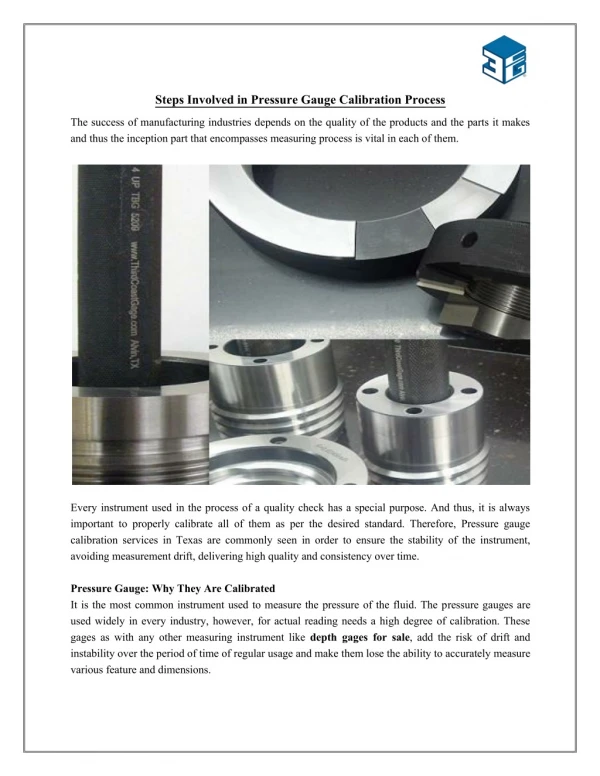
What is the Dicing System? The Dicing system is generally utilized in the semiconductor bundling industry to isolate Silicon wafers into individual chips. Several processes are used in the production of integrated circuits to transform raw materials into packaged components that may be assembled into electronic circuits. To put it another way, the Dicing process is a procedure for separating the silicon wafer and the die. During the wafer dicing system, Wafers are mounted utilizing PVC or tape, which has a tacky support and holds the wafer on a metal edge. The procedure is carried out in a clean area where the air is constantly circulated because even the tiniest dust particles could harm the intricate circuits imprinted on a wafer. Depending on the use, this tape has various properties. For smaller die sizes, UV-curable tapes are utilized, while the non-UV dicing tape is used for higher die sizes. When a wafer is sliced, the die remains on the tape until it is removed by machinery like a die bonder. Most of the time, the dies are square or rectangular. They can also take on other shapes, depending on the wafer dicing technique used.
Attaching a Wafer to the Tape Frame Plasticized PVC film adhesive tape is one of the most dependable materials used in the assembly and handling of semiconductor devices. It is widely used in processes including wafer row expansion, wafer scribing, sawing, and fracturing as well as die transfer and bonding. Understanding the fundamentals of defining and working with tape is beneficial for the user given the widespread and growing use of processing tape with a wide range of application characteristics. The success or failure of using plasticized PVC film tape for semiconductor processing depends on the choice of tape. During the 300mm wafer dicing service, the process known as Wafer Tape Mounting is carried out. It is a step in the creation of semiconductors. The wafer is mounted on the tape, which is attached to the metal frame, during this procedure. Temperatures in the Wafer Mounted area are normally maintained between 32 and 38 degrees. The corresponding basic subsidiary regulator is utilized in this gear to control the temperature as per fabricating process prerequisites. The temperature should be back between 32°C and 38°C after the wafer mounting process is finished. At this temperature, the tape becomes more pliable, making it possible to make uniform and conformal contact with the wafer. The uniform tape strain on the wafer in the film frame is produced by the tape’s expansion and contraction as it cools. This effect will take place if the elasticity of the tape is uniform.
Process for Wafer Dicing with Blades An adhesive-backed tape is used to attach wafers to a metal frame. The vacuum chuck of the dicing saw is used to hold the wafer frame in place. The wafer is put on the throw region and embedded into the axle region where a grating precious stone edge turns at 15,000 to 30,000 RPM. The abrasive eats away at the wafer as the blade turns. DI To enhance cut quality and remove cutting debris, water is supplied to the blade. 40 to 100 psi should be the DI water pressure. A diamond bond matrix covers the sharpening diamond particles so that they can freely enter the material, reduce loads, and provide excellent cut quality. The removal of material that is clogging the spaces between a loaded blade’s abrasive particles is yet another reason to dress it. The diamonds must be fully protruded and exposed for them to easily enter the cutting material. In most cases, untidy dicing edges will push the material, resulting in high loads, high cutting temperature or intensity, and poor cut quality. Due to the 300mm wafer dicing service, blade damage is possibly likely.
Micro-Washing Method Alkali, metals, heavy metals, and organic contaminants can all be removed from semiconductor components using a method that does not destroy the wafer. As a result, cleaning semiconductor wafers is an essential step in the production of electronics. Using etch cleaning techniques as well as wet chemistry-based cleaning technologies. One of the most common steps in the 300mm wafer dicing service is the cleaning of the wafer. Cleaning processes are turning out to be progressively difficult as innovation develops and gadgets shrivel. Not only should the wafers be cleaned, but also the used machinery and equipment should be cleaned. Wafer contaminants include, among other things, organic and inorganic pollutants, impurities, and particles with diameters ranging from 0.10 to 20 microns. Solvents, acids, and water are all necessary components for wet cleaning. In the examination, dry-cleaning use lasers, sprayers, or ozonated synthetic substances.
Die Sorting and Inspection of Wafers The kick-the-bucket arranging and review framework examines passes on before gathering, permitting clients to quickly distinguish any blunders during the dicing system of wafer-level bundles. Wafer-level bundling advances have developed, bringing new materials into the cycle that can break during dicing, for example, low k materials in fan-in wafer-level bundles. By rapidly detecting defects during die sorting, this solution aids chip manufacturers in reducing production risk and improving output quality for the subsequent assembly stage. With each node, the technology for detecting flaws on a wafer, wafer inspection, becomes more difficult, challenging, and costly. This is because of shrinkage in the process, difficulties in design, and the introduction of new materials. Additionally, the most challenging aspect of using today’s optical inspection equipment is identifying defects below 30 nm. There are two kinds of wafer inspection. Despite significant drawbacks, both styles are frequently regarded as complementary. While optical inspection tools are rapid, their resolution isn’t very good. E-beam and single-beam inspection techniques offer greater resolution but are slower. A novel kind of multi-beam e-beam inspection system is being developed by some suppliers. These advancements vow to find minute imperfections more quickly than the present single e-pillar instruments by using different shafts. Source: https://brandmisk.com/different-steps-involved-in-dicing-process/