Download
1 / 40
400 likes | 411 Views
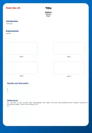
This remote display is a outdoor truck scale remote display of the highest quality with full stainless steel body with IP65 standard, which is the world"s first ultra light LED display that has a viewing angle of 170 degrees and is crystal clear directly under sunlight. The remote display offer unmatched flexibility with its smart data recognition system compatible with indicators from major international indicator brands.<br><br>

E N D
GM8895 User’s Manual GM8895-VER-120102 48019050211001 110605070006
GM8895 Remote Display ©2012 , Shenzhen General Measure Technology Co., Ltd reserve all copyright. Without permission from Technology Co., Ltd,Any corporations or person must not copy, spread, record or translate into other language by any forms. Our company reserved the right to update user’s manual without additional notice to make perfect for customers. Thus please visit our website or contact with our service person to get update information. Website:http://www.szgmt.com Shenzhen General Measure
GM8895 Remote Display Foreword All of staffs from Shenzhen General Measure Technology Co., Ltd appreciate that you buy GM8895 Remote Display. In order to ensure your installation and wiring correctly, and take full of advantage on capability and function of the remote display, please read the user’s manual seriously and keep it properly for reference in the future.
GM8895 Remote Display CONTENT 1. General Instructions............................................................................ 1 1.1 Function features....................................................................... 1 1.2 Front panel illumination.............................................................1 1.3 Specification................................................................................2 2. Installation and Wiring.........................................................................3 2.1 Installation...................................................................................3 2.2 Open Remote Display...............................................................4 2.3 Inside Structure Diagram..........................................................5 2.4 Power/Communication Terminals Connection......................6 2.4.1 Power Cable Connection...............................................6 2.4.2 Communication Terminals Connection.......................6 3. Application Illumination.......................................................................8 3.1 Mirror Display Function.............................................................8 3.2 Communication Address Setting.............................................8 3.3 Communication Mode Setting..................................................9 3.4 Wireless Communication Function.......................................10 3.5 Red&Green lights output control function............................11 4. Working Mode....................................................................................12 4.1 Normal Display Mode..............................................................12 4.2 Mirror Display Mode................................................................13 5 .Communication Protocols................................................................14 6. Hanging Board Dimension Diagram...............................................32
GM8895 Remote Display 1. General Instructions GM8895 Remote Display is one of our independent innovation instrument for end show, which is used with various electronic weighing instruments at wide application:AD-4321 、 TOLEDO & Fairbanks R2500 、 、 Rinstrum, UMC600 、 series、GSE60 series、WI-125、 、WI-127、 、 AD-4323 、 、 GSE50 、 、DF1500 and so on. 1.1 Function features Detachable sunlight shelter to ensure clear vision in sunlight Dustproof and Waterproof housing – IP65, Easy installation RS232/RS485/current loop communication terminals Wireless Communication Function Mirror Display mode 1.2 Front panel illumination P 1-1 Communication Waterproof communication lines with remote display (NOT used for wireless mode). Signal Input: connect 1 1
GM8895 Remote Display Waterproof Power Cable Input: Connect power cable with remote display. Lock Buckle: Lock front and back board of remote display. Wireless Communication Sign Receiver: Receive weighing data from the indicator in wireless communication (optional function). 2 3 4 Main display: Display weighing data, including decimal point and minus sign. Weight unit lb: Weight unit is pound. t : Weight unit is ton. Kg:Weight unit is kilogram. Status light GROSS: Light for gross weight. NET: Light for net weight. MOTION: Light for motion. 1.3 Specification Specification Temperature -10~40℃ Max Humidity 95%R.H Power Supply Communication interface AC90V~260V RS232/485; 0~20mA current loop; Wireless(915MHz) 900×280×106(mm)(without sunlight shelter) 903×296×257(mm)(with sunlight shelter) 50~60Hz Dimension Dimension 2
GM8895 Remote Display 2. Installation and Wiring 2.1 Installation User can fix Remote Display on wall or strong metal stand according to actual application. The following instruction is to fix on wall for example. 1. Fix hanging board on wall (Suggesting using M6 dilatants bolts to fix hanging board). Please Hanging Board Diagram. refer Dimension P29 P 2-1 2. Put Remote Display on the hanging board fixed on wall. P 2-2 3. Ensure Remote Display to be hanged firmly, and then screw tightly fix Remote Display on hanging board. to P 2-3 3
GM8895 Remote Display 2.2 Open Remote Display Please open Remote Display as following instruction before connecting power cable /communication terminals or related operation, and then begin to run. 1. Loose four lock buckles (location as following diagram). P 2-4 2. Open the front panel of Remote Display, install built-in bracket in Remote Display to support front panel. P 2-5 3. The left area is for these electric circuit boards, now begin to connect power cable / communication terminals or operate correlatively. P 2-6 4
GM8895 Remote Display 2.3 Inside Structure Diagram GM8895 Remote Display inside structure and its connection diagram are following: P 2-7 5
GM8895 Remote Display 2.4 Power/Communication Terminals Connection 2.4.1 Power Cable Connection P 2-8 N:Null wire G:Ground wire L:Live wire 2.4.2 Communication Terminals Connection The connection between the indicator and GM8895 remote display are different according to different communication mode. Please refer Chapter 3.3 (P9) for communication mode. (1)RS232 communication mode The connection diagram between weighing the indicator and GM8895 remote display are following: P 2-9 6
GM8895 Remote Display (2)RS485 communication mode The connection diagram between weighing the indicator and GM8895 remote display are following: P 2-10 (3)0~20mA Electric current loop The connection diagram between weighing the indicator and GM8895 remote display are following: P 2-11 7
GM8895 Remote Display 3. Application Illumination 3.1 Mirror Display Function With this function, weighing data can be displayed in reversed format to suit special requirement. Push SW2 switch(blue switch)D1 to ON, Then power on again, weighing data will be displayed in reversed format. 3.2 Communication Address Setting Through D3、D4、D5、D6 of SW2 switch (blue switch) to set communication address, after setting, power on again. Near number side is defined 0, and near “ON” side is defined 1. Please restart GM8895 to make new setting effect. The address table: Display D3 D4 D5 D6 Address 0 0 0 0 0 0 0 0 1 1 0 0 1 0 2 … … … … … 1 1 1 1 15 For example: If present SW2 switches are same as right Diagram, the current remote Display address is “3”. When Remote Display address is “0”, it works in single communication mode, and communication; while the address is not “0”, it works in multiple communication mode, and address should be matched when communication. address is meaningless for 8
GM8895 Remote Display 3.3 Communication Mode Setting Set desirable serial communication mode by adjusting SW1 and JP1, JP2 location on main board. After setting finished, please restart GM8895 to make new setting effect. (1)RS232 mode Push SW1 switches (red switch) D3 and D4 to ON, others to OFF. And push JP2 switch to 232 side. (2)RS485 mode Multiple communications can be preceded by RS485 mode, which means more GM8895 remote displays can be connected in one 485 communication net, but display weighing data separately. Push SW1 switches (red switch) D3 and D4 to ON, other to OFF. And push JP2 switch to 485 side. (3)0~20mA current loop mode Please run GM8895 Remote Display first, and then run connected weighing the indicator. Put SW1 switches (red switch) D3 and D4 to OFF, others to ON. 9
GM8895 Remote Display 3.4 Wireless Communication Function (1)Wireless communication is a transmitter by point-to-point style, thus no cables connected between the indicator and GM8895 remote display to reduce site wiring. (2)Within the range of visibility, the reliable transmission distance is >2500m when the height is greater than 2m from ground; Within the range of visibility, the reliable transmission distance is >2800m when the height is greater than 5m from ground. P 3-1 1. For wireless communication, only 4 lines are necessary to connect, other 5 lines are reversed, please do NOT connect. See above diagram for details. 2. Suggest communicating requirement or sign-disturbed application. by cables in no special Attention: SW2 switches (blue switch) D2 is reserved for manufactory, must be OFF at any case to ensure remote display run well. 10
GM8895 Remote Display 3.5 Red&Green lights output control function GM8895 has 2 on/off data output interfaces to control the red&green lights.(Optional function) Interface definition diagram: Output L-G Green light L-R Red light GM8895 uses optoelectronic isolation technology to transfer the ON/OFF data. This needs 24V DC power supply that is provided from outside, through the 24V (DC+) and the 24G (DC-).The I/O signal input is low level effective.The output is open-collector output. The driving current can reach 1A. 11
GM8895 Remote Display 4. Working Mode 4.1 Normal Display Mode 1. When GM8895 remote display power on,it will run self-test first. Main display twinkle “0.0.0.0.0.0.” at one second alternation. at numbers “9.9.9.9.9.9.” and P 4-1 2. When GM8895 remote display connects with the indicator properly, and can receives weighing data from the indicator, GM8895 will display the current weighing data within some time. For example, if current weighing data is net weight 1980Kg, then remote display will show as following: P 4-2 Note: if the connection is not correct, or present data haven’t been received from the indicator, so GM8895 will show “------”. P 4-3 12
GM8895 Remote Display 4.2 Mirror Display Mode If Mirror Display switch is ON, all weighing value will be reversed on GM8895. The following diagram indicates above mirror display: 1. P 4-1 corresponding mirror display as follows: P 4-4 2. P 4-2 corresponding mirror display as follows: P 4-5 3. P 4-3 corresponding mirror display as follows: P 4-6 13
GM8895 Remote Display 5. Communication Protocols GM8895 Remote Display can connect with present famous weighing indicators, and can suit serial interface parameters (baud rate/communication protocol) automatically, which means it possess auto-recognized function for communication protocols of various weighing indicators. GM8895 remote display have three kinds communication modes: RS232/RS485, and 0~20mA current loop. Any communication mode can suit following communication protocols, and also can suit user-defined communication protocols. Support baud rates: 2400/4800/9600/19200 The remote display is terminal display instrument connected with weighing equipment, so only the sign, numbers, decimal point and unit characters can be shown correctly, not to display text characters. 14
GM8895 Remote Display 5.1 A&D-4321( (AD-4323) ) Data format: 5.2 TOLEDO & Fairbanks R2500 Data format: 15
GM8895 Remote Display Status byte A: Bits0, 1, 2 indicate the position of decimal point; Bits3, 4 are the division factor. bit X00 X0 X X.X X.XX X.XXX X.XXXX X.XXXXX 0 0 1 0 1 0 1 0 1 1 0 0 1 1 0 0 1 1 2 0 0 0 0 1 1 1 1 division factor1 1 0 division factor 5 1 1 bit division factor 2 3 4 5 6 7 0 1 Always logic 1 Always logic 0 Odd/even bit Status byte B: bit 0 Status Gross=0 Net =1 + =0 - =1 1 Normal = 0 Overflow=1 2 Stable =0 Unstable =1 3 4 5 6 7 Pounds (lb)=0 Kilo Grams(kg)=1 Always logic 1 Power up=1 Normal = 0 Odd/Even bit 16
GM8895 Remote Display Status byte C: Status bit 0 1 2 3 4 5 6 7 Always logic 0 Always logic 0 Always logic 0 = 0 Always logic 0 Always logic 1 Normal= =0 Normal= Print enabled= = 1 Tare enabled= = 1 Odd/Even bit 17
GM8895 Remote Display 5.3 Data format: UMC 600 5.4 Data format: GSE 60 series (GSE 50 series) 18
GM8895 Remote Display 5.5 Data format: WI-125 5.6 Data format: WI-127 19
GM8895 Remote Display 5.7 Data format: DF1500 series 5.8 Data format: Rinstrum A protocol 20
GM8895 Remote Display 5.9 Data format: Rinstrum C protocol 5.10 Data format: Rinstrum PC protocol 21
GM8895 Remote Display 5.11 Data format: Bilanciai D800 Cb protocol 5.12 Data format: HBM WE2107 EOP 6 protocol 22
GM8895 Remote Display 5.13 Data format: Gedge C2 protocol 5.14 Data format: Gedge C3 protocol 23
GM8895 Remote Display 5.15 Data format: Protocol NO.1 5.16 Data format: Protocol No.2 5.17 Data format: Protocol No.3 Note: The display timeout is disabled, which means that the message will remain on the display until new data is sent. 24
GM8895 Remote Display 5.18 Date format: Protocol No.4 5.19 Data format: Protocol NO.5 5.20 Data format: Protocol No.6 25
GM8895 Remote Display 5.21 Data format: Protocol No.7 5.22 Data format: Protocol NO.8 Status S1 and S2 are 0~F ASCII code: S1 S1 Status 0 Tare=0,preset Tare=1 Only used in Net mode. 1 Motion=0,Stable=1 2 Not COZ=0,COZ=1 3 Gross=0,Net=1 S2 0 1 2 S2 Units=kg Units=g Units=T Status Weight longer than string, Display will be blanked. 5 26
GM8895 Remote Display 5.23 Protocol NO.9 Data format: 5.24 Protocol No. 10 Data format: 27
GM8895 Remote Display 5.25 Data format: Protocol NO.11 5.26 Data format: Protocol No.12 5.27 Data format: Protocol No. 13 28
GM8895 Remote Display 5.28 Protocol No. 14 Data format: 5.29 Systec protocol Data format: 29
GM8895 Remote Display 5.30 GM Multiple communication protocol Data format: Rinstrum PC protocol mode, protocol and used GM in Multiple multiple address communication communication setting refers to illumination P8. are which communication 30
GM8895 Remote Display 5.31 Fidelity Protocol Data format: Header 1 Header 2 Data (7) , Sign , Unit CR LF Here: Header1:2bits ST —— Stable sign, S=0x53 US——Unstable sign, U=0x55 S=0x53 , —— Separator sign: 0x2C Header2: : 2bits NT —— Net weigh mode, N=0x4E GS ——Gross weight mode, G=0x47 S=0x53 Sign —— the digits show (0x2D) for negative data and space (0x20) for positive data. Data ( ( 7 ) ) —— 7 bits weight value including point(0x2E). If there is no decimal point, then the first character is space. Unit:2bits kg——kilograms k=0x6B lb——pounds l=0x6C b=0x62 ; _t —— ton _=0x20 t=0x74 CR —— Carriage Return 0x0D LF —— Line Feed 0x0A T=0x54 T=0x54 decimal g=0x67 ; 31
GM8895 Remote Display 6. Hanging Board Dimension Diagram P 6-1 32