Download
1 / 25
250 likes | 278 Views
Explore the impact of soft errors on adder circuits, analyze error rates, propose modeling techniques and experimental methodologies to improve robustness.

E N D
Soft errors in adder circuits Rajaraman Ramanarayanan, Mary Jane Irwin, Vijaykrishnan Narayanan, Yuan Xie Penn State University Kerry Bernstein IBM
Talk Overview • Introduction • Soft errors • Introduction • Impact on data-path circuits • Modeling soft errors in logic circuits • Experimental setup and methodology • Error injection mechanism • Adder circuits considered • Methodology • Results • Conclusions and Future work (Lessons learned)
Talk Overview • Introduction • Soft errors • Introduction • Impact on data-path circuits • Modeling soft errors in logic circuits • Experimental setup and methodology • Error injection mechanism • Adder circuits considered • Methodology • Results • Conclusions and Future work (Lessons learned)
Introduction • Soft errors, which are transient errors caused due to external radiations, affected mainly memory circuits. • Soft error rates (SER) in data-path structures and combinational logic have been increasing due to: • Continuous device scaling. • Voltage scaling and increased speed. • increasing pipeline lengths.
Introduction • Adder circuits form an integral part of data-path. • Hence, in this work, we • Analyze SER in different types of adder circuits. • Analyze the effect of voltage and frequency scaling on SER. • Experimented techniques to improve the error rates in adder circuits based on above results.
Talk Overview • Introduction • Soft errors • Introduction • Impact on data-path circuits • Modeling Soft errors in logic circuits • Experimental setup and methodology • Error injection mechanism • Adder circuits considered • Methodology • Results • Conclusions and Future work (Lessons learned)
Soft errors - Introduction • Soft errors or transient errors are circuit errors caused due to excess charge carriers induced primarily by external radiations. • These errors cause an upset event but the circuit it self is not damaged.
Soft errors - Impact on data-path circuits • In data-path circuits, an error is caused when the pulse generated by a particle is latched on at the output by a flip-flop. • Here, the critical charge (Qcritical),can be defined, as the minimum charge required to latch on to the pulse. • There are three masking effects in combinational circuits that affect the propagation of any given pulse: • Logical masking • Electrical masking • Latching window masking
REG I STERS REG I STERS Particle strike I1 No Soft error 1 I2 0 Soft error D 1 O1 I3 1 B I4 1 0 E I5 1 O2 I6 0 C I7 Effect of electrical masking Masking effects in data-path
Modeling soft errors * Simulated 150 MEV Proton-induced charge collection for 90 nm and 130 nm bulk technologies; per-bit SER per unit collection *Courtesy - K. Bernstein
Modeling soft error in logic circuits • Massengill et al. developed a model for a tool, which would predict the probability of an error occurring in a given combinational circuit. • Probability that a random particle hit (resulting in a current pulse) at a node N in a clock cycle C will be latched on by the output latch or flip-flop (PSFC,N). • Probability of soft errors occurring in a given circuit can be determined using the above probability.
Modeling soft error in logic circuits • In this work, we propose a model that can accurately models the above probability. • We borrow the term “Timing Vulnerability” defined in the work by S. Mukherjee et al. • This is defined as the fraction of time in a clock cycle in which a given node in a circuit is vulnerable (tv). • For example, a latch has a tv of 50%. • Thus, PSFC,N = ∑ PQcoll * tv , where PQcoll is the collected charge at a given node.
Talk Overview • Introduction • Soft errors • Introduction • Impact on in data-path circuits • Modeling Soft errors in logic circuits • Experimental setup and methodology • Error injection mechanism • Adder circuits considered • Methodology • Results • Conclusions and Future work (Lessons learned)
Error injection mechanism • Based on the models provided by previous works, • We modeled our current pulse as an exponential wave form with a pulse width of 50 ps in our HSPICE simulations. • Charge colleted at a node can be determined using the following expression: • Q= ∫ Iddt,where Id =Drain Current.
S0 S1 S2 S3 S0 S1 S2 S3 C1 C2 C3 C1 C2 C3 C0 C0 P0 P1 P2 P3 P0 P1 P2 P3 € € € € € € € € € P0,G0 P1,G1 P2,G2 P3,G3 P0,G0 P1,G1 P2,G2 P3,G3 (a) Brent-kung (B-K) (b) Kogge-stone (K-S) Adder Designs Considered
Methodology • Our analysis consists of: • Measuring Qcritical at different nodes affecting different outputs in B-K adders. • Comparing B-K with K-S and Ripple Carry (RC) adders. • Measuring Qcritical and tv after scaling voltage and frequency. • Next we consider techniques to improve the above two quantities to increase the robustness of adders: • Use a Flip-Flop with better tv values. • Using a Semi-dynamic Flip-Flop (SDFF) instead of a Transmission gate Flip-Flop (TGFF) used initially. • Increase threshold voltage, which increases Qcritical. • All circuits were custom designed and laid out in 70nm technology.
Talk Overview • Introduction • Soft errors • Introduction • Impact on data-path circuits • Modeling Soft errors in logic circuits • Experimental setup and methodology • Error injection mechanism • Adder circuits considered • Methodology • Results • Conclusions and Future work (Lessons learned)
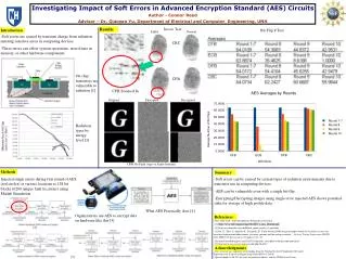
Results – B-K adders • For B-K adders (at node C0): • Qcritical’s for a node to cause a flip at all the sum outputs are similar. • Qcritical for all outputs flipping together is higher.
Adder comparisons • For B-K and K-S, Qcritical at a node for flipping different outputs are comparable while RC has progressively increasing Qcritical. • Qcritical is smaller in K-S adders due to shortest path carry chains. • Also KS adders have greater area susceptible to soft errors due to larger number of carry cells. • B-K adder has more nodes that fan’s out equally to many outputs • Hence, a single particle strike at a node can cause multi-bit errors.
Voltage and Frequency scaling • The adders were run at 1 GHz, 0.833GHz and 0.5 GHz with 1V, 0.8 V and 0.6V as supply voltages respectively. • As both voltage and frequency are scaled, Qcritical reduces slightly at many nodes. • Reducing frequency reduces tv, but reduction in Qcritical plays a much important role.
Optimization Techniques • Using Flip-Flop with lesser set-up and hold time (SDFF) • Improves timing vulnerability. • Also improves Qcritical for multi-bit errors. • Increasing threshold voltage • Increases Qcritical as it increases the gain of the logic circuit. • But it increases the timing vulnerability also.
Conclusions and lessons learnt • The timing vulnerability determines the occurrences of multi-bit errors in adders. • Trade-offs have to be considered in using different type of adders. • K-S adders have lesser Qcritical and higher soft error rate. • Multi-bit errors can be more common in B-K adders • Voltage and frequency scaling worsens the soft error rate. • Techniques to improve Qcritical and tv were presented. • Trade-offs in choosing these techniques.
References • L. W. Massengill, A. E. Baranski, D. O. V. Nort, J. Meng, and B. L. Bhuva. Analysis of Single-Event Effects in Combinational Logic – Simulation of the AM2901 Bitslice Processor. IEEE Trans. on Nuclear Science, 47(6):2609–2615, December 2000. • S. K. Reinhardt and S. Mukherjee. Transient Fault Detection via Simultaneous Multithreading. International Symposium on Computer Architecture, pages 25–36, July 2000.