Download

1 / 27
280 likes | 575 Views
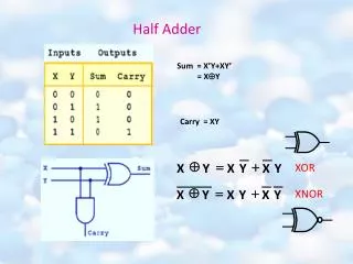
Half Adder . Sec. 3.10 Sec. 4.5, 4.12. Schedule. Test #1: Beginning of March. Outline. Transition from Verilog to Digital Logic Observations Verilog Lesson Application: Half Adder. Observations. Lab submissions are due at the beginning of the next lab, i.e. the following Thursday.

E N D
Half Adder Sec. 3.10 Sec. 4.5, 4.12
Schedule Test #1: Beginning of March
Outline • Transition from Verilog to Digital Logic • Observations • Verilog Lesson • Application: Half Adder
Observations • Lab submissions are due at the beginning of the next lab, i.e. the following Thursday. • Path to the files/`timescale • Need One bit file per input • Power Supply: Tie the common reference ground.
`timescale Comment `out timescale Each time interval is one second. Need to update the path! $readmemb(“./bit_str_a_0.txt”,t_A); Default directory: verilogSandBox
Need One bit file Per Input G1 E C F G3 G4 D G2 Need one bit file per input! Remember to pull the numbers out of the registry.
Lessons on Verilog • Verilog • Running Command Line Verilog • $monitor– output the data to the monitor • $fmonitor—save data to an output file • Module/module test bench template • assign • Bitwise logic operator
Two Ways of Running Verilog Running Verilog Using the GUI Writing Output to a file Advantage: Avoid the GUI Disadvantage: hard to visualize an input pattern
Running Verilog at Command Prompt • $monitor • $fmonitor
Monitor Numbers Monitor numbers
Run Verilog Using Command-line $monitor only displays the results when A changes. Actual sequence: 101011001011…
%0d verses %d (“time=%d”, $time…..) (“time=%0d”, $time…..)
Writing Output to a file 1. Declare a file pointer 2. Open a file, specify the file name 3. Use $fmonitor to write to a file 4. Close the file after 1000 time intervals 5. Finish the simulation
Module Template module module_name ( , , ) endmodule Input, output wires reg Program Body
Module Test BenchTemplate //`timescale 1 ms /1 us module module_tb_name ( , , ) endmodule Input, output wires reg Define the test bench Call on the module
Your First Verilog Program module fig3p37 (A,B,C,D,E); output D,E; input A,B,C; wire w1; and G1(w1,A,B); not G2(E,C); or G3(D,w1,E); endmodule And, notor are primitive gates. The output of a primitive gate is always listed first. The inputs can be listed in any order. G1 is an instance of the and gate.
Rewrite the Program Using assign Use & for AND operation Use tilda (~) for the INVERT operation Use | for the OR operation You can think of a wire as a wire in a circuit where actual voltages Could be measured.
Keyword: assign • assign: the assignment is said to be sensitive to the variables in the RHS expression because anytime a variable in the RHS changes during the simulation, the RHS expression is reevaluated and the result is used to update the LHS. • RHS: Right Hand Side of = • LHS: Left Hand Side of = • wire elements are the only legal type on the left hand side of an assign statement. (More about this next time)
Bitwise Logic Operation • Bitwise means 1 bit at a time
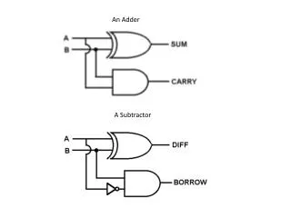
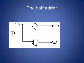
Derivation of ∑ (ES112 Slides) • Question: What primitive best implements ∑? • Inputs: A, B • Outputs: ∑=
Derivation of Carry Out(ES112 Slides) • Question: What primitive best implements Co? • Inputs: A, B • Outputs: Co =A∙B
Limitation of a Half Adder A half-adder does not account for carry-in.
Module Template module module_name ( , , ) endmodule Input, output wires reg Program Body Verilog program