Download
1 / 57
580 likes | 1.23k Views
Topologies - II. Overview. Express Cubes Flattened Butterfly Fat Trees DragonFly. Express Cubes. The Problem Node delay dominates wire delay Pin densities are not as high as wiring densities In a k- ary n- cube , n , k , and W are all related

E N D
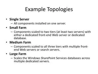
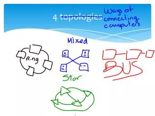
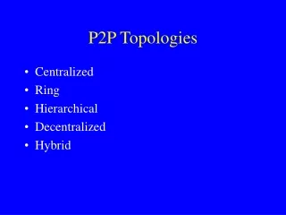
Overview • Express Cubes • Flattened Butterfly • Fat Trees • DragonFly
Express Cubes • The Problem • Node delay dominates wire delay • Pin densities are not as high as wiring densities • In a k-ary n-cube, n, k, and W are all related • Consequently networks are node limited rather than wiring limited • Unused capacity • Goals: • design a network that can make use of the unused wiring capacity • Approach the wire delay lower bound
Express Links Interchange box Wire delay = i.Tw express channel i = 4 Non-express latency Express latency
Balancing Node and Wire Delay • Reduce the node delay component of latency • Express channel length chosen to balance wire delay and node delay • For large D, the latency is within a factor of 2 of dedicated Manhattan wire latency • Pick i based on average distance and relationship between wire delay and node delay Interchange box Wire delay = i.Tw express channel
Balancing Throughput and Wiring Density • Exploit available wiring density to move beyond pin-out limitations • Consider wiring density of the substrate • More complex interchanges • Good utilization of express channels • Routing on express links
Balancing Throughput and Wiring Density • Simpler interchange box design • Routing in a dimension • Uneven traffic distribution across links
Hierarchical Express Channels • Messages in the express segment are dominated by node latency • Reduce by making this latency growth as logarithm • Logarithmic for short distances and linear for long distances • Port assignment for messages at each level • Combine advantages of direct and indirect networks • Routing in three phases: ascent, cruise, descent
Latency Behavior • Saw tooth pattern reflects latency jumps • Hierarchical channels smoothes out latency variations
Reducing Pin Out • Implementing interchanges with constant pin-out • Small latency penalty • These can be further reduced at the expense of a few more hops
Implementing Multiple Dimensions N N N N N N N N N N N N N N N N • Pinout of interchange boxes is kept constant • Messages have to descend to local channels to change dimensions
Summary • Push to create networks limited by wire delay and wire density • For long distances, latency approaches that of a wire • Increase the bisection width of the network • Baseline of k-ary n-cubes – efficient use of bisection width • Hierarchical express cubes combines logarithmic delay properties with wire efficiency and locality exploitation • What happens when high radix routers become feasible?
Flattened Butterfly • Pin bandwidth and pin-out have improved over the years • Low dimensional networks do not make good use of this greater I/O bandwidth • Implications of improved off-chip bandwidth?
Reading Assignment • J. Kim, J. Balfour, and W. J. Dally, “Flattened Butterfly Topology for On-Chip Networks,” Proceedings of MICRO 2007 • J. Kim, W. J. Dally, and D. Abts, “Flattended Butterfly: A Cost Efficient Topology for High Radix Networks,” Proceedings of ISCA 2007
Topology Tradeoff ? Combination of desirable properties MINs Clos Network • Retain the desirable properties of MINs • Logarithmic diameter • Cost • Exploit the properties of folded Clos Networks • Path diversity • Ability to exploit locality
Analysis • Logarithmic path lengths of MINs are offset by lack of path diversity and ability to exploit locality • Need to balance cost (switches, links/cables/connectors), latency and throughput • Reduce the channel count by reducing diameter • Reduce the channel count by concentration • Better properties are achieved by paying for the above with increased switch radix
Another Look at Meshes • Trade-off wire length and hop count • Latency and energy impact • Take advantage of high radix routers short hop count short wires
Key Insight • Goal is to balance serialization latency and header latency • Meshes only reduce serialization latency • FB trades serialization latency for header latency via higher radix switches
Using Concentrators Can be integrated as a single switch • Better balance of injection bandwidth and network bandwidth • How often do all processors want to communication concurrently? • Significant reduction in wiring complexity Figure from J. Kim, J. Balfour, and W. J. Dally, “Flattened Butterfly Topology for On-Chip Networks,” Proceedings of MICRO 2007
Construction • Note that the inter-router connections are determined by permutations of the address digits • For example in the above figure (a)
On-Chip Structure • Structurally similar to generalized hypercube • Attempts to approach the wire bound for latency • Latency tolerant long wires (pipelined, repeated) • Deeper buffers Figure from J. Kim, J. Balfour, and W. J. Dally, “Flattened Butterfly Topology for On-Chip Networks,” Proceedings of MICRO 2007
Router Optimizations S D Non-minimal routing Using Bypass Channels Figures from J. Kim, J. Balfour, and W. J. Dally, “Flattened Butterfly Topology for On-Chip Networks,” Proceedings of MICRO 2007
Connectivity • Each switch i in a stage is connected to j for m = 0 to k-1
Properties • For a k-ary n-flat with nodes we have routers in dimensions with router radix • Built for size • Need high radix routers Figure from J. Kim, J. Balfour, and W. J. Dally, “Flattened Butterfly Topology for On-Chip Networks,” Proceedings of MICRO 2007
Routing • Basic dimension order traversal • However in MINs all paths are of length • In FB, only necessary dimensions need be traversed (remember binary hypercubes!) • Number of shortest paths is factorial in the number of differing dimensions • In the MIN, dimension order is fixed • Non-minimal routing for better network-wide load balancing • Enables performance equivalent to flattened Clos
Comparison to Generalized Hypercubes • Use of router bandwidth • Concentration in a k-ary n-flat produces better link utilization and lower cost • Example: Use 1K nodes and radix 32 switches • GHC – (8,8,16) • FB – one dimension • Load balanced non-minimal routing in FB 0 0 0 1 1 1 0 31 31 31 If BW is matched, serialization latency will dominate
Comparison • For 1024 nodes • Flattened butterfly • Radix 32 switches and two stages • Folded Clos • Radix 64 switches and two stages • Binary hypercube • 10 dimensional hypercube • Trade-off analysis will keep the bisection width constant
Fat Trees • The seminal paper by C. Leiserson, “Fat Trees: Universal Networks for Hardware Efficient Supercomputing,” IEEE Transactions on Computers, October 1985. • Simple engineering premise: a network topology that has the advantages of the binary tree without the problems
Reading Assignment • Xin Yuan et. al., “Oblivious Routing for Fat-Tree Based System Area Networks with Uncertain Traffic Demands,” SIGMETRICS 2007, Section 2.2 (until property 1). • Recommended C. Leiserson, “Fat Trees: Universal Networks for Hardware Efficient Supercomputing,” IEEE Transactions on Computers, October 1985.
Backward Forward Fat Trees: Basic Idea • Alleviate the bandwidth bottleneck closer to the root with additional links • Common topology in many supercomputer installations
0 1 2 3 4 5 6 7 8 9 10 11 12 13 14 15 Alternative Construction • Nodes at tree leaves • Switches at tree vertices • Building crossbars with simpler switches • Total link bandwidth is constant across all tree levels, with full bisection bandwidth • This construction is also known as having constant bisection bandwidth © T.M. Pinkston, J. Duato, with major contributions by J. Filch
0 1 2 3 4 5 6 7 8 9 10 11 12 13 14 15 FT(4,4): Sub-trees • Built with constant radix (m) switches and L levels • Can be viewed as a less costly way of building crossbar switches X. Lin, Y. Chung and T. Huang, “A Multiple LID Routing Scheme for Fat-tree Based InfiniBand Networks,” IEEE IPDPS 2004
FT (4,4) spine sub-tree 0 1 2 3 4 5 6 7 8 9 10 11 12 13 14 15 X. Lin, Y. Chung and T. Huang, “A Multiple LID Routing Scheme for Fat-tree Based InfiniBand Networks,” IEEE IPDPS 2004
Properties • The properties follow from multistage interconnection networks • Number of inputs as a function of m and L • Number of switches as a function of m and L
Generalized Fat Trees • Networks with variable bisection bandwidth • Asymmetric use of switch radix between successive levels • Can construct expanders and concentrators • GFT (L,m,w) • L levels • Bandwidth ratio of m:w between levels Reference: S. R. Ohring, M. Ibel, S. K. Das, M. J. Kumar, “On Generalized Fat-tree,” IEEE IPPS 1995
Revisiting the Clos Network 0 0 1 1 2 2 3 3 4 4 5 5 6 6 7 7 8 8 9 9 10 10 11 11 12 12 13 13 14 14 15 15
Folded Clos Network 0 • Network is effectively folded into itself to produce a fat tree • Consequently often referred to as a folded Clos Network • Note this is also equivalent to a bidirectional Benes network • Rearrangeable when 1 2 3 4 5 6 7 8 9 10 11 12 13 14 15
Implications • The connectivity of this class of fat trees are equivalent to that of a crossbar • Realizing the performance of a crossbar is another matter • Recall it is not strictly non-blocking (crossbar) but rather rearrangeable • Packet scheduling and congestion management are key to performance • Achievable performance a function of the communication pattern
Basic Routing • Compare addresses of source and destination • Digit position of the first difference identifies the stage/level is to turn around. • Any path up the tree • Deterministic routing down the tree • Load balanced routing randomizes the up path
Dragonfly Topology • How do we build networks that scale to >106 nodes? • Technology to date had prescribed low dimensional networks • Target – Exascale computing systems • Topology challenge • Reconciling trade-offs between diameter, switch radix, and cost • What is a feasible radix to use vs. need for scalability? • Indirect topology
Reading Assignment J. Kim, W. J. Dally, S. Scott, and D. Abts, “Technology-driven highly scalable Dragonfly topology,” Proceedings of the International Symposium on Computer Architecture, 2008
Dragonfly • Increasing pin bandwidth has moved the design point • More channels, smaller diameter rather than less channels higher bandwidth/channel • Increases the number and length of cables • Network cost proportional to number of channels, especially global channels • Reduce the number of global channels • Use new signaling technology for long channels optical signaling • Engineering optimizations to increase the effective switch radix
Topology Basics • One level hierarchy • Traffic limited to one global hop • Flexible definition of intra-group interconnection h global channels (a-1) local channels inter-group network intra-group network G0 G1 Gg 0 1 a-1 0 1 P-1
Properties • Switch radix • Effective radix (group radix) • Number of groups • Number of nodes
Topology Variations • The inter-group network • Downsizing: redistribute the global channels amongst the groups • Upsizing: move to multiple global hops • Rightsizing: increase virtual radix to maintain single hop property, e.g., radix 64, 2D k-ary n-flat intra-group network and 256K nodes • The intra-group network • Trade-off local hops vs. physical radix
More on Properties • Bisection bandwidth follows inter-group network • Pin-out (radix) is a design parameter • Defines network scale and diameter • Defines local (group) hop count From J. Kim, et.al, “Technology-driven highly scalable Dragonfly topology,” ISCA 2008
Balanced Design • How do we think about values of parameters a, p, and h? • Balancing traffic on global and local channels • Balancing cost • Trade-off swicth radix with number of global channels (cables)
Routing • Minimal routing takes at most three steps • Route to the router within the source group that connects to the correct destination group (multi-hop?) • Route across the global channel to the correct destination group • Route to the correct destination router within the destination group that connects to the destination (multi-hop?) • Does not work well under adversarial patterns • Use Valiant’s 2-phase routing algorithm • Route to a random intermediate group • Route to the desination
Summary • Topology designed to scale to large numbers of nodes (>106) • Sensitive to a hierarchy of interconnect delays and costs • Exploits increased pin-bandwidth in emerging technologies • We will return to more sophisticated routing algorithms later