Download
1 / 14
160 likes | 677 Views
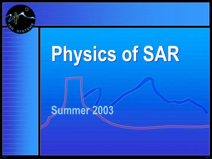
Physics of SAR. Summer 2003. SAR Radar. SAR. Synthetic-Aperture Radar. RAdio Detection And Ranging. Radar - Transmits its own illumination • a "Microwave flashlight" . Radar Imaging. Form a terrain image using a radar in a . Problem. moving airborne/orbital vehicle.

E N D
Physics of SAR Summer 2003
SAR Radar SAR Synthetic-Aperture Radar RAdio Detection And Ranging Radar - Transmits its own illumination• a "Microwave flashlight"
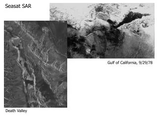
Radar Imaging Form a terrain image using a radar in a Problem moving airborne/orbital vehicle Simplest Approach - Real-Beam Imaging Radar Example: P lan P osition I ndicator (PPI) 0° Range Azimuth Azimuth 270° 90° Individual image points (pixels) must be discriminated in two dimensions, range and azimuth 180° PPI Display
Range Discrimination 2D d t t t D d D d The transmitted pulse travels at the speed of light 109 feet/second Þ1 nanosecond/foot Round trip "radar time" Þ 2 nanoseconds/foot (Dd = 2 feet Þ Dt = 4 nanoseconds) But target returns overlap if targets are separated by less than t/2
Shorter Pulses So for better range resolution, just make SHORTER the transmitted pulse However , the shorter pulses must somehow SAME ENERGY transmit the to the target = = = SHORTER HIGHER As the pulse gets , the peak power gets Peak power gets MUCH too high beforepulse length even approaches high resolution Problem
Coded Pulses Transmit a long coded pulse that can be decoded (compressed) afterreception into a much shorter pulse Solution f f 1 2 t Linear F.M. (Frequency Modulation) Linear Swept Frequency "Chirp" Note: A typical 200 microsecond pulse extends over more than 16 nautical miles in radar space
Pulse Compression Frequency f 2 D f Transmitted/Received Pulse f 1 t Time t t 1 2 Frequency f 2 Variable Delay Line"Compression" Filter D f f 1 Delay Time t 0 Frequency f 2 1 Decoded / "Compressed“Output D f D f f 1 Time Pulse compression ratio = pulse "time-bandwidth product"
Pulse CompressionAdvantages • Range resolution independent of transmit pulse length • Transmit long pulses • Keep peak power comfortably low • Set range resolution with transmitted bandwidth • Resolution inversely proportional to bandwidth • 300 MHz ñ 2-foot resolution • 600 MHz ñ 1-foot resolution • Resolution independent of slant range
Azimuth Considerations SAR Synthetic-Aperture Radar Antenna beamwidth is inversely proportional to the number of wavelengths in its length (aperture) l L q = radians L c l = f
l R L l R L Azimuth Discrimination Flight Path L D d L R Real-beam imaging radar • As the collection vehicle moves along the flight path, targets are detected as they move in and out of the antenna pattern • But target returns overlap if the targets are separated in azimuth by less than the antenna beamwidth • So Achievable azimuth resolution decreases with range
Narrower Beamwidth • So for better azimuth resolution, just make the antenna beam NARROWER! • Generate more wavelengths in the antenna aperture by lengthening the antenna or by shorting the wavelength (increasing the frequency) • However, very LONG antennas are difficult to carry and position, and very HIGH frequencies limit performance in weather and at long ranges Antennas get MUCH too long and frequencies MUCH too high before the beamwidth even approaches high resolution Problem
Synthetic-Aperture Synthesize a long antenna apertureusing a physically short antenna Solution SAR Synthetic-Aperture Radar Store the data collected sequentially and coherently across a long aperture and then process the data to synthesize a full aperture collection
Azimuth Considerations Flight Path SyntheticallyProcessedAperture(LS) Synthetically Processed Beam l LP PhysicalAntenna(LP) l/LS Real Beam
Synthetic-ApertureAdvantages • Increased angle of collection on a target allows increased resolution • High resolution capability with short physical antenna • Processed aperture size is easily increased as imaging distance increases • Azimuth resolution independent of slant range