Download
1 / 34
340 likes | 574 Views
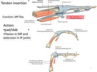
Insertion Devices. Toshi Tanabe Insertion Device Group Leader Accelerator System Advisory Committee October 14-15, 2010. Outline. Changes / Progress since last ASAC review ID Table / Official Schedule Progress on Each Device R & D (PrFeB, IVMMS, AGU, VST) FY11 Goals and Milestones

E N D
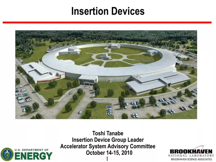
Insertion Devices Toshi Tanabe Insertion Device Group Leader Accelerator System Advisory Committee October 14-15, 2010
Outline • Changes / Progress since last ASAC review • ID Table / Official Schedule • Progress on Each Device • R & D (PrFeB, IVMMS, AGU, VST) • FY11 Goals and Milestones • Conclusions Acknowledgement: ID group members: C. Kitegi, J. Rank, D.A. Harder, T. Corwin, V. Ruchinsky, G. Rakowsky Part-time members: O. Chubar, C. Spataro, P. He, F. Huston Accelerator Physics: J. Bengtsson, S. Krinsky, A. Blednykh, L.H. Yu Vacuum Group: Dick Hseuh Mechanical Group: V. Ravindranath
Progress since ASAC09 • New Hires • One Mechanical Technician (T6): Todd Corwin, hired on December 2009 • One Assistant Scientist (S1): Charles Kitegi, hired on July 2010 • One Electrical Engineer (P5): Vlad Ruchinsky, hired on March 2010 • 2 ME and 1 Sci positions are open now (thanks to NIH funding) • Technical Status of Systems • PM Damping Wiggler (DW) Vendor selected by the panel. Waiting for DOE approval. • In-Vacuum Undulator (IVU) Preliminary mechanical design completed. • Elliptically Polarized Undulator (EPU) RFP is to be issued. • Three Pole Wiggler (3PW) RFP has been issued (deadline for proposal: Nov. 8) • Magnet Development Laboratory (Insertion Device Magnet Measurement Facility) • Hall probe bench has been completed and waiting for installation. • Environmental enclosure almost complete (estimated completion on October 28, 2010)
Changes since ASAC09 Damping Wiggler Parameters (90mm period/12.5mm gap 100mm/15mm) have changed due to the concern of excessive heating of vacuum chamber by misplace beam. PCR_10_140 approved to change “In Vacuum Magnetic Measurement System” from in-house development to a large procurement PCR_10_124 approved to add “Evolution of In-Vacuum Undulators for IXS (IVU-22)”
Recent ID Review (9/14-15,2010) Recommendations • Revisit misalignment tolerances task force established • Impedance calculations for IVUs accelerator physics group • Include magnetic performance requirement for larger gaps than operating gap for DW change order after the contract • Cost analysis and performance justification for BNL reference design with CPMU upgradability • Reallocate engineering assets from IVU to EPU RFP is ready • Option for multiple production for 3PW contract or obtain design right include the option with currently prepared RFP • Detailed interface specifications for ID controls controls group • Clarify the long term objectives of the ID group
DW-Magnet Temperature Rise Peak temperature ~ 45 °C Max Temperature of Magnets in steady state ~45°C
DW Reference Design by Radia • lw=100mm with side magnets (Br=1.28T, gap=15.0mm, Keff / g = 2.80 mrad) • Integral of By2 on-axis for one period in longitudinal direction 0.1586 T2.m • Effective K 18.2 • DA for 90mm wide pole (J.Bengtsson)
EU49 (Reference-Design) Parameters D1 D2 A B A C M5 M5 MT1 M3 M5 M3 M5 M3 MT2 M3 M5 M3 M5 M3 M3 Termination Magnet Thicknesses and Spaces: ΔD1 = 8.15 mm ΔD1-C = 4.47 mm ΔC = 6.11 mm ΔC-D2 = 0.65 mm ΔD2 = 3.82 mm Undulator Parameters: Br = 1.25 (NdFeB) Main Magnet Dimensions: 34 mm (H) x 34 mm (V) x 12.25 mm (L) Longitudinal “Air-Gap” between Main Magnets: 50 μm Horizontal Gap between Magnet Arrays: 1 mm Period: 49.2 mm Number of Full Periods: 38 Length: ~1930 mm (without “Magic Fingers”, ~1960 mm with “MF”) Minimal Gap: 11.5 mm D1 D2 A C B A A B C A B A D2 D1 B Suggested Modular Structure Vertical First Field Integral Horizontal First Field Integral Shift = λu/2 M3 - 3 magnet module (A+B+A) M5 - 5 magnet module (B+A+B+A+B) Shift = λu/4 (parallel) 1st Field Integral [G.cm] M3 + M5 = 2 periods Shift = λu/4 (anti-parallel) 1st Field Integral [G.cm] Shift = λu/4 (anti-parallel) Ex. Estimated Residual Field Integrals (40 periods without Correction Coils) Shift = 0 Gap [mm] Gap [mm]
In-Vacuum Undulator • X25-MGU based IVU lu=20mm, Minimum Gap=5.0mm, 3m Long • Baseline Design Uses Conservative NdFeB (Br=1.12T, Hcj=30kOe) Radia Model NSLS MGU-X25 Opera 3D Model Demag. Analysis
Gap Drive Structure Assembly End View Front View Section A-A
Magnet Core Assembly and Cross Sections Bi-metal Transition Flange Crossover Coupler Cooling Platen Coolant Channel Magnet Array Ass’y Return Outlet Coolant Channel Cross Flow Supply Inlet Cross Flow C L UHV Thermometry Distribution Current Mt’l Spec: EB-Welded 2219-T87 Aluminum Platen, 5082 Aluminum Magnet Array R&D Mt’l Spec: OFHC Copper Platen (anneal to 20-30% Syp), 316L Stainless Magnet Array
Three Pole Wiggler (3PW) • Requirements: • More than 2 mrad of radiation fan above 1T field • Use a special inconel (25 mm outer vertical) chamber • Fixed gap and removable from one side of the chamber • Simple and economical • Magnetic Design (Central Pole Gap=28mm) • Br=1.25T • Permendur Center Pole • Soft Iron (1006) Side Poles • Rectangular Magnets • Main Magnets: 120 x 41. x 90 mm • Center Pole: 120 x 23 x 65 mm • End Poles: 101. x 45 x 86 mm Radia Model Tosca Model
List of “Off-baseline” Devices • IVUs for NIH Funded Beam Lines (funded) • 2 Canted IVUs in a short straight section similar to SRX • One standard U20 • Another device to be specified • NEXT-MIE Devices (near term: details unknown yet) • Several standard IVUs (expected) • SCW (4.5T ~ 6T) • Long Period EPU? • Type-II Beamlines • NEXT-II • NxtGen • Biological and Environmental Research (BER)
New Technology (Off-baseline) • Adaptive Gap Undulator • Different period length / gap depending on the magnet position in Z • Various issues such as impedance effect by the steps and kick compensation in each joint section, etc. remain to be solved. • SCU • 14mm period, B=1.68T, 2m long • APC NbTi wire is now available • Both LTS/HTS version will be investigated. • CPMU (PrFeB) • Proto-type test shows 19% increase of Br from RT to 77K • 17mm period, Br (@77K)=1.5T, 2.6m long • Bakeable magnets may be produced.
FY11 Goals and Milestones DW Contract award (November 4th ) 3PW Contract to be awarded (Est. 3rd week of November) EPU Contract to be awarded (Est. 2nd week of December) Completion of ID-Magnetic Measurement Facility (to be completed in Dec 2010: on track) SRX-IVU21 Contract to be awarded (January 2011: on track) IVU20 Contract to be awarded (May 2011: on track) IXS-IVU22 Contract to be awarded (Est. June 2011)
Summary • Damping Wigglers • A vendor has been selected and details of the contract is negotiated. • 3PW & EPU • RFP has been issued. • IVU • Reference mechanical design is completed by BNL for SRX-IVU • Impedance optimization with the design of the transition region design is still required. • IXS-IVU22 requires special design for long straight installation • ID-MMF • Enviromental enclosure will be completed on October 18th, 2010 as planned. • Hall probe bench, Helmholz coil, Calibration Dipole will be installed by the end of December • R&D and Future Devices • IVMMS proposals have been received by two vendors. • PrFeB based CPMU R&D is being carried out. • Design work for AGU has just started.
1m OFHC Platen Proto-type • Integrated cooling channel closed by the friction stir welding technique
AGU Example for IXS Beam Line Magnetic Field Single-Electron Spectral Intensity at ~9.1 keV (on axis) λu = 22 mm K ≈ 1.5 IVU22 G ≈ 7 mm λu≈ 22.87 mm 20.98 mm 19.74 mm K ≈ 1.45 1.57 1.66 G ≈ 7.74 mm 6.23 mm 5.32 mm Spectral Flux through 100 μrad (H) x 50 μrad (V) Aperture λu≈ 22.54 mm 20.24 mm 19.64 mm 21.26 mm K ≈ 1.47 1.62 1.66 1.55 G ≈ 7.46 mm 5.68 mm 5.25 mm 6.45 mm λu≈ 22.87 mm 19.59 mm High-β Straight I = 0.5 A K ≈ 1.45 1.67 G ≈ 7.74 mm 5.21 mm • O. Chubar
PrFeB Magnet 77K Measurement • PrFeB (53CR v2 magnet) Magnet Arrays • Cut from a large piece M vector uniformity is poor Sorted by signature method • Period Length = 14.5mm, Gap=4.85mm • RT measurement on granite Hall probe bench (Gap=4.85mm) for the reference • RT & LN2 (77K) measurement on VTF • Increase of ~19 % in Br
2m SCU-Field measurement setup (courtesy of A. Grau of KIT) Measurement setup parts under construction • Local field measurements via Hall samples on a sledge • Position (z-direction) measurement with laser interferometer • Zero Gauss chamber for zero check of Hall sample calibration (possible after every thermal cycle) • possibly in addition 2 Helmholtz coils for linearity check of Hall sample calibration (not shown) • Integral field measurements with stretched wire technique (CuBe wire Ø125µm) • Position adjustment for stretched wire in x-y-direction via linear stages with encoders
Tunnel Cross Section of a Long Straight Section 1330.82mm (Minimum)