Download
1 / 14
140 likes | 275 Views
The Field of View of a Thin Lens Interferometer. Pathlengths from “in phase” positions: Top Channel 2Bsin q +(F-Bsin q )/cos f ’ Bottom Channel (F+Bsin q )/cos f. 2Bsin q. B. 2 Channels in Phase here. B. Bsin q. f ’. F. q. f. Nulled here. Baseline=2B.

E N D
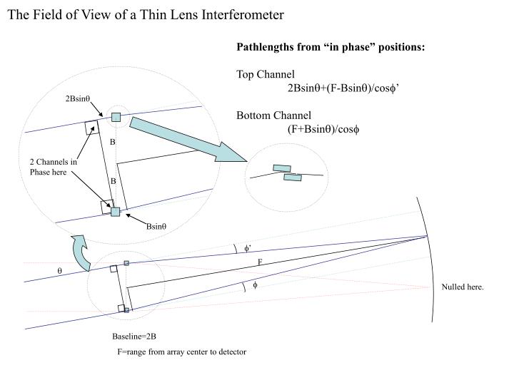
The Field of View of a Thin Lens Interferometer Pathlengths from “in phase” positions: Top Channel 2Bsinq+(F-Bsinq)/cosf’ Bottom Channel (F+Bsinq)/cosf 2Bsinq B 2 Channels in Phase here B Bsinq f’ F q f Nulled here. Baseline=2B F=range from array center to detector
Pathlengths from “in phase” positions: Top Channel 2Bsinq+(F-Bsinq)/cosf’ Bottom Channel (F+Bsinq)/cosf The Field of View of a Thin Lens Interferometer: Approximations APPROXIMATIONS: DeflectionAngles of each Channel:f’~f Cos Approximation: cosf ~ 1-f2/2 Taylor Expansion: q/(1+dx) ~ q(1-dx) Also Assumed: Internal workings of both lenses are identical! OPD between top and bottom channels: OPD ~Bf2sinq f’ F q f Nulled here. Baseline=2B F=range from array center to detector
Q: Given the OPD between the channels, what is the condition to NOT seriously distort a fringe on the detector? A: OPD < l/10 Note that this condition also defines the field of View for an interferometer of this type. • OPD between top and bottom channels: • OPD ~Bf2sinq • qFOV=l/(10f2B) • = lF2/(10B3) NOTE: This FOV calculation makes no assumptions about maximum graze Angles. Therefore, at most, the FOV will be ~0.5 degrees due to graze restrictions.
Designing a Mission 1:Baseline, Focal Length, FOV, and Formation Tolerances are derived. What angular resolution at what wavelength do you want? qres, l Tightest Formation Flying Tolerance between optics s/c = s. “Lateral” What is the smallest X-ray pixel size(mm) you can imagine? s The baseline (2B) needs to be: 2B = l/ qres The Focal Length (F) needs to be: F = s/qres Longitudal Formation Flying Tolerance between optics s/c = 4/5(s/l)2 qresB The FOV will be: FOV = 4/5(s/l)2 qres
Designing a Mission 2: What angular resolution at what wavelength do you want? qres, l Tightest Formation Flying Tolerance between optics s/c = s. “Lateral” What is the smallest X-ray pixel size(mm) you can imagine? s The Difference Here is That we will have fringes 10x bigger than the CCD pixel Size. The baseline (2B) needs to be: 2B = l/ qres The Focal Length (F) needs to be: F = 10 s/qres Longitudal Formation Flying Tolerance between optics s/c = 80(s/l)2 qresB The FOV will be: FOV = 80(s/l)2 qres
Mirror Module Dimensions • The Mirror modules are pairs of flat (better than l/100) mirrors. • One mirror is fixed, the other has pitch (~mas) and yaw (arcminute) control. • The module also has the ability to adjust the spacing of the mirrors at the nm level to introduce ~ angstrom pathlength control. • Thermal control consistent to maintain optical figure (~0.1 degrees). • There is structure to hold the module together.
The Mass of Glass 1: msin(g) If a mirror length is “m”, and the graze angle is “g”, then the width of the mirror is m*sin(g)- in order to have square effective areas for each module. The effective area of one module will be: Amodule= (r*m*sin(g))2 Where r is the reflectivity off one mirror. m Some Numbers: r~0.8 g~2 degrees sin(g)~1/30 => Amodule~ m2/1400
The Mass of Glass 2: msin(g) The “1/6” rule suggests that the thickness of the mirror be about 1/6th the length in order to preserve figure. If the density of the mirror is s, then the mass of the glass of one module is: Mglass= sm3sin(g)/3 m m/6 • Some Numbers: • s~2.5 g/cc • sin(g)~1/30 • Mglass~ m3/16 grams • (m in cm)
The Mass of Glass 3: msin(g) Some Numbers: s~2.5 g/cc sin(g)~1/30 The ratio of mass to effective area becomes: Mass/area = r2ms/(3sin(g)) m m/6 • NOTE- this mass estimate is for glass only. There may be some scaling of masses for structure and actuators- but that is not considered here.
Actuator Requirements: The pitch control should be to the some fraction of the diffraction spot size. dq~l/(m*sin(g))~30l/m ~ 6 mas for m=100 cm, 62 mas for m=10cm ~ 30 nm of control for anysize mirror. The range of pitch control should be able to accommodate the range of baselines over the range of focal lengths. qmax~ B/F = l/(20s) ~ 1 arcsecond of range ~ 5x10⁻⁶m of linear range for a mirror of length m. where s=CCD pixel size
What would one of these modules look like? msin(g) msin(g) m m/3 + msin(g) 3/2m+d 2(w+gap)+msin(g) By 2(w+gap)+msin(g)+m/3+actuator+encoder ASSUME: w+gap~5 cm Encoder+encoder~5cm Sin(g)~1/30 -->(10cm+m/30)x(15cm+m/3+m/30) -->m=30cm-> 13cmx26cm m/6 Gap~msin(g) Yaw ontrol Pitch Control