Download
1 / 24
240 likes | 469 Views
Calibration of single-photon detectors from spontaneous parametric down-conversion. Justin Ripley Columbia University, New York, NY Fermi National Accelerator Laboratory, Batavia, IL Mentor: Carlos Escobar. August 9, 2012. Overview. What is Spontaneous Parametric Down-Conversion (SPDC)?

E N D
Calibration of single-photon detectors from spontaneous parametric down-conversion Justin Ripley Columbia University, New York, NY Fermi National Accelerator Laboratory, Batavia, IL Mentor: Carlos Escobar August 9, 2012
Overview • What is Spontaneous Parametric Down-Conversion (SPDC)? • Calibration using SPDC • What are Silicon Photomultipliers (SiPMs)? • Experimental set up • Preliminary Results • Current Work • Future Work
SPDC: Basics ks • One photon (pump) enters a nonlinear crystal; two photons (signal and idler) emerge • Energy and momentum conserved • ωp = ωs + ωi • kp= ks + ki θsignal kp θidler ki • “Spontaneous”: no final states in initial configuration ( ~ 1 in 109 photons down-converted) • “Parametric”: crystal does not add/subtract energy/momentum from process (elastic scattering) • “Down-Conversion”: frequency of pump photon lowered
SPDC: Nonlinearity and Quantum Components • Quantum Component • Send in intense pump beam: E(p)eiωpt + c.c. • Spontaneous fluctuations of the vacuum state amplified in nonlinear crystal Nonlinear Component • Optical susceptibility tensor: P(E)= χ(1)ijEj + χ(2)ij’k’Ej’Ek’ + … • Second order term: χ(2)ijkEjEk Three wave mixing • Second order term: χ(2)ijk EiEk • Take two waves: (E(1)eiω1t + c.c. + E(2)eiω2t + c.c.) • Run through crystal, among final wave states get: • ~(E(1))(E(2))*ei(ω1 -ω2)t • ~(E(2))(E(1))*ei(ω2 –ω1)t (IvanoRuo-Berchera, Advanced Science LettersVol. 2, 407–429, 2009)
SPDC: Phase Matching • Select for specific exit angles for signal beams at specified wavelengths • kj= (2π/c)νjnjej • νpnpep= νsnses + νiniei • nj depends on orientation of optical axis (rotation of linear term χ(1)) • Crystal used is Beta-Barium Borate (BBO); is uniaxial (one optical axis) neee ks Θoptical axis Θsignal Θidler kp ki BBO Crystal *B. Boeuf, D. Branning, I. Chaperot, E. Dauler, S. Guérin, G. Jaeger, A. Muller, and A. Migdall, “Calculating characteristics of noncollinear phase matching in uniaxial and biaxial crystals,” Optical Engineering, vol. 39, no. 4, April 2000.
Calibration using SPDC Conjugate Detector Efficiency: ηc X Y BBO Crystal Z Idler Signal 3˚ Pump Beam 3˚ Down-Converted Cone of Light Trigger Detector Efficiency: ηt • Assume N down converted (correlated) photon pairs produced and reach Conjugate and Trigger detectors • Klyshko Method • Photons detected by trigger: Nt = Nηt • Photons detected by conjugate given a detection by trigger : Nc= Nηtηc • Efficiency of conjugate detector: ηc = Nc/Nt • Absolute calibration • Modify for background counts
Including sources of background in Calibration formula • ηc = calibrated detector efficiency • Nc = measured number of coincidence counts during calibration run • Nt = measured number of single counts for trigger detector during calibration run • Bc= Estimated background accidental coincidence counts • Bt= Estimated background single trigger counts • Background run • Measure background counting rate (Bt’) for trigger detector with no laser on • Accidental coincidences run • Measure coincidence counting rate (Bc’) for detector with laser on with a time delay • Calibration run • Measure single counts on trigger, coincidence counts for time period T • Bc= Bc’T • Bt= Bt’T
What are SiPMs? • Matrix of silicon p-n junction diodes • Operate in Geiger mode Pros • High gain • Single photon resolution • Good time resolution • Low Bias Voltage • Low power consumption • Cons • High dark pulse rate • Cross talk • Lots of afterpulsing (Pictures courtesy of SensL: http://www.sensl.com/downloads/ds/TN%20-%20Intro%20to%20SPM%20Tech.pdf )
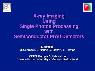
General Experimental Layout TOP VIEW (not to scale) (6)Beam Dump (1) Ga-As laser (405nm) (2) Iris (7) 810nm Filter (9) SiPM 1 (3) Iris (5) BBO 3˚ 3˚ (4) Iris (10) SiPM 2 (8) 810nm Filter 1m • Readout from detectors went to a FPGA SiPM general readout board (Rubinov and Fitzpatrick) • Low bandwidth processing • BBO crystal optical axis aligned for 3 degree phase matching
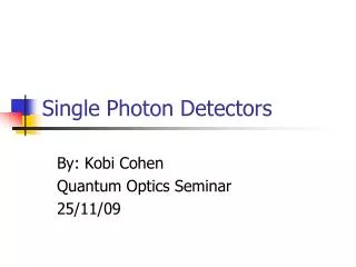
Experimental Set Up (as of 8/1/2012)
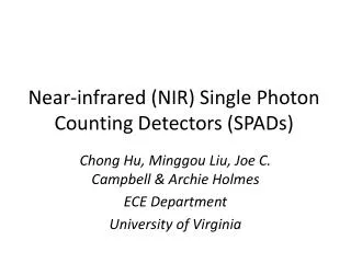
Preliminary Results (7/27/12) • Detectors used for alignment • Single pixel SiPMs (100μm) • Calibrated detectors will have ~103 or more pixels • Data processed in ~18.8 ns long bins • Channel 0: Trigger detector • Channel 1: Conjugate detector
Current Work: Alignment • Align detector mounts • “Scanning” alignment detectors and search for global maxima in count rates around calculated down-converted beam location
Current Work: Noise • Electronic • Hard to distinguish electronic signals from photons in a short time frame (ΔtΔν ~ 1) • Low bandwidth board to cut high frequency noise • Measure background rates (should include electronic noise) • House FPGA in Faraday cage • Background stray photons • Laser fluorescence • Weaker laser • Mirrors with higher reflectivity in near ultraviolet • Dark box with 810nm filters covering beam entrances • Dark Pulses, Afterpulsing • Intrinsic to SiPMs • Measure during accidentals and background calibration runs • Possibly cool down detectors
Future Work/Goals • Proof of principle with alignment of detectors along one axis • Align detector mounts along two axis (x, y) • Initially calibrate SiPMs at 810nm • Calibrate other photodetectors • Other wavelengths possible via rotation of crystal optical axis or use of shorter wavelength pump laser
Acknowledgements • Carlos Escobar • Paul Rubinov • Adam Para • Donna Kubik • Paul Kwiat