Download
1 / 19
190 likes | 371 Views
2-Hardware Design Basics of Embedded Processors. Outline. Introduction Combinational logic Sequential logic Custom single-purpose processor design RT-level custom single-purpose processor design. Digital camera chip. CCD. CCD preprocessor. Pixel coprocessor. D2A. A2D. lens.

E N D
Outline • Introduction • Combinational logic • Sequential logic • Custom single-purpose processor design • RT-level custom single-purpose processor design
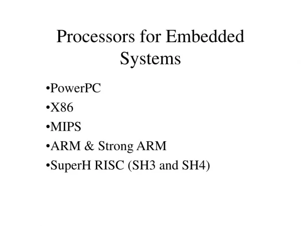
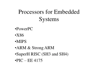
Digital camera chip CCD CCD preprocessor Pixel coprocessor D2A A2D lens JPEG codec Microcontroller Multiplier/Accum DMA controller Display ctrl Memory controller ISA bus interface UART LCD ctrl Introduction • Processor • Digital circuit that performs a computation tasks • Controller and datapath • General-purpose: variety of computation tasks • Single-purpose: one particular computation task • Custom single-purpose: non-standard task • A custom single-purpose processor may be • Fast, small, low power • But, high NRE, longer time-to-market, less flexible
source gate Conducts if gate=1 drain 1 gate oxide IC package IC source channel drain Silicon substrate CMOS transistor on silicon • Transistor • The basic electrical component in digital systems • Acts as an on/off switch • Voltage at “gate” controls whether current flows from source to drain • Don’t confuse this “gate” with a logic gate
source source gate Conducts if gate=0 gate Conducts if gate=1 drain drain pMOS nMOS 1 1 1 x x y x F = x' y F = (xy)' x F = (x+y)' y 0 x y 0 0 NOR gate inverter NAND gate CMOS transistor implementations • Complementary Metal Oxide Semiconductor • We refer to logic levels • Typically 0 is 0V, 1 is 5V • Two basic CMOS types • nMOS conducts if gate=1 • pMOS conducts if gate=0 • Hence “complementary” • Basic gates • Inverter, NAND, NOR
x x F F x x x F F y x F x x x x x x y y y y y y F F F F F F y 0 0 0 1 F y 0 0 0 0 0 0 0 0 0 0 0 0 1 0 1 0 0 1 1 1 1 0 0 0 0 0 0 0 1 1 1 1 1 1 0 1 1 0 0 1 1 1 1 1 1 1 0 0 0 0 0 0 1 1 0 0 1 0 1 1 1 1 1 1 1 1 1 1 1 1 0 0 1 1 0 1 x x x F x F F F y y y F = x y XNOR Basic logic gates F = x Driver F = x y AND F = x + y OR F = x y XOR F = x’ Inverter F = (x y)’ NAND F = (x+y)’ NOR
B) Truth table C) Output equations D) Minimized output equations Outputs Inputs y bc y = a'bc + ab'c' + ab'c + abc' + abc a b c y z 00 01 11 10 a 0 0 0 1 0 0 0 0 0 0 0 0 1 0 1 1 1 1 1 1 z = a'b'c + a'bc' + ab'c + abc' + abc 0 1 0 0 1 0 1 1 1 0 y = a + bc z 1 0 0 1 0 bc 00 01 11 10 1 0 1 1 1 a 0 0 1 0 1 1 1 0 1 1 1 1 1 1 1 1 0 1 1 1 E) Logic Gates z = ab + b’c + bc’ a y b c z Combinational logic design A) Problem description y is 1 if a is to 1, or b and c are 1. z is 1 if b or c is to 1, but not both, or if all are 1.
A B I1 I0 I(m-1) n n n … n bit, m function ALU S0 n-bit, m x 1 Multiplexor S0 … … S(log m) n S(log m) n O O O = I0 if S=0..00 I1 if S=0..01 … I(m-1) if S=1..11 less = 1 if A<B equal =1 if A=B greater=1 if A>B O = A op B op determined by S. O0 =1 if I=0..00 O1 =1 if I=0..01 … O(n-1) =1 if I=1..11 sum = A+B (first n bits) carry = (n+1)’th bit of A+B A B I0 A I(log n -1) B n n … n log n x n Decoder n-bit Adder n-bit Comparator With enable input e all O’s are 0 if e=0 With carry-in input Ci sum = A + B + Ci May have status outputs carry, zero, etc. … n O(n-1) O1 O0 carry sum less equal greater Combinational components
I n load shift n-bit Register n-bit Shift register n-bit Counter clear I Q n n Q Q Sequential components Q = lsb - Content shifted - I stored in msb Q = 0 if clear=1, I if load=1 and clock=1, Q(previous) otherwise. Q = 0 if clear=1, Q(prev)+1 if count=1 and clock=1.
D) State Table (Moore-type) C) Implementation Model B) State Diagram Outputs Inputs Q1 Q0 a I1 I0 x x a Combinational logic 0 0 0 0 0 x=1 x=0 a=0 a=0 0 I1 0 0 1 0 1 0 3 a=1 0 1 0 0 1 I0 0 0 1 1 1 0 a=1 a=1 1 0 0 1 0 0 Q1 Q0 1 0 1 1 1 1 2 1 1 0 1 1 1 a=1 1 1 1 0 0 State register a=0 a=0 x=0 x=0 I0 I1 Sequential logic design • Given this implementation model • Sequential logic design quickly reduces to combinational logic design A) Problem Description You want to construct a clock divider. Slow down your pre-existing clock so that you output a 1 for every four clock cycles
E) Minimized Output Equations F) Combinational Logic Q1Q0 I1 00 01 11 10 a 0 0 1 1 a 0 I1 = Q1’Q0a + Q1a’ + Q1Q0’ x 0 1 0 1 1 Q1Q0 I0 00 01 11 10 a 0 1 1 0 I1 0 I0 = Q0a’ + Q0’a 1 0 0 1 1 x I0 Q1Q0 00 01 11 10 a 0 0 1 0 x = Q1Q0 0 0 0 1 0 Q1 Q0 1 Sequential logic design (cont.)
HDL based design (review examples) • D_Latch • Greatest common divisor circuit (GCD)
1-D_Latch: VHDL module examples --D_latch.vhd library IEEE; use IEEE.STD_LOGIC_1164.all; ENTITY D_latch IS PORT ( d,clk : IN STD_LOGIC; q : OUT STD_LOGIC); END D_latch; ARCHITECTURE concurrent OF D_latch IS SIGNAL qwire,qb : STD_LOGIC; SIGNAL sb,rb,db: STD_LOGIC; BEGIN sb <= d nand clk; rb <= not (d) nand clk; qwire <= sb nand qb; qb <= rb nand qwire; q<=qwire; END concurrent; ARCHITECTURE behaviour OF D_latch IS BEGIN Process (d,clk) variable qwire,qb : STD_LOGIC; variable sb,rb,db: STD_LOGIC; BEGIN sb := d nand clk; rb := not (d) nand clk; qwire := sb nand qb; qb:= rb nand qwire; q<=qwire; END Process; END behaviour;
1-D_Latch: VHDL module examples ARCHITECTURE behaviour2 OF D_latch IS BEGIN Process (d,clk) variable qwire,qb : STD_LOGIC; variable sb,rb,db: STD_LOGIC; BEGIN if (clk='1') then q<=d; end if; END Process; END behaviour2; - - test file (tD_latch.vhd) library IEEE; use IEEE.STD_LOGIC_1164.all; entity DlatchTB is end DlatchTB; Architecture TB_arch of DlatchTB is component D_latch port (d,clk: in STD_LOGIC; q: out STD_LOGIC); end component; signal dT,clkT, qT: STD_LOGIC; begin U1: D_latch port map (dT, clkT, qT); process begin report "Begining test bench for D latch" severity note; dT<='0'; clkT<='0'; wait for 10 ns; dT<='0'; clkT<='1'; wait for 10 ns; dT<='1'; clkT<='1'; wait for 10 ns; end process; end TB_arch;
2- Greatest common divisor circuit (GCD) • continually subtracting the smaller of the two numbers, A or B, from the largest. • Stop when the smallest =0 • file: gcd_test_data.txt 21 49 7 25 30 5 19 27 1 40 40 40 • file: gcd_test_data_hex.txt 15 31 7 19 1E 5 19 27 1 28 28 28
Greatest common divisor circuit (GCD): C code #include <stdio.h> main () { int A_in, B_in, A, B, Swap, Y, Y_Ref; FILE *file_pointer; file_pointer = fopen("gcd_test_data.txt", "r"); while (!feof(file_pointer)) { fscanf (file_pointer, "%d %d %d\n", &A_in, &B_in, &Y_Ref); A = A_in; B = B_in; if (A != 0 && B != 0) { while (B != 0) { while (A >= B) { A = A - B; } Swap = A; A = B;B = Swap; } } else A = 0; Y = A; //should be equal to Y_Ref } }
Greatest common divisor circuit (GCD): Verilog module module GCD_ALG(A_in,B_in,Y); parameter Width = 8; input [Width-1:0] A_in, B_in; output [Width-1:0] Y; reg [Width-1:0] A, B, Swap, Y; always @(A_in)// or B) begin begin A = A_in; B = B_in; if (A != 0 && B != 0) while (B != 0) begin while (A >= B) A = A - B; Swap = A; A = B; B = Swap; end else A = 0; Y = A; end endmodule
Greatest common divisor circuit (GCD): Verilog module module test_GCD; // Test GCD algorithm parameter GCD_tests = 4; parameter Width = 8; reg [Width-1:0] A_in, B_in, Y_Ref; integer N; integer SimResults; reg [Width-1:0] AB_Y_Ref_Arr[1:GCD_tests*3]; wire [Width-1:0] Y; GCD_ALG U0 (A_in,B_in,Y); initial $monitor (" GCD: A=%d B=%d Y=%d. Y should be %d", A_in, B_in, Y, Y_Ref); initial begin $readmemh("gcd_test_data_hex.txt", AB_Y_Ref_Arr); SimResults = $fopen("gcd_simres.txt"); // Open simulation results file for (N=0; N<GCD_tests; N=N+1) begin A_in = AB_Y_Ref_Arr[(N*3)+1]; B_in = AB_Y_Ref_Arr[(N*3)+2]; Y_Ref =AB_Y_Ref_Arr[(N*3)+3]; #10; $fdisplay (SimResults, " GCD: A=%d B=%d Y=%d. Y should be %d", A_in, B_in, Y, Y_Ref); end $fclose (SimResults); $finish; end endmodule
Greatest common divisor circuit (GCD): VHDL module ENTITY GCD IS PORT ( A_in,B_in : IN integer range 0 to 15; Y : OUT integer range 0 to 15 ); END GCD; ARCHITECTURE behaviour OF GCD IS BEGIN Process (A_in,B_in) variable A, B, Swap: integer range 0 to 15; BEGIN A := A_in;B := B_in; for i in 0 to 15 loop if (A /= 0 and B /= 0) then if (A>=B) then A := A - B; else Swap:= A; A := B; B := Swap; end if; else A:=0; end if; end loop; Y<=A; END Process; END behaviour;