Download
1 / 15
220 likes | 562 Views
In-track Measuring System for Wheel Profiles on Railway Vehicles. Overview. Principle Of Operation Of Point Laser Triangulation Sensor Scanning Laser Sheet Of Light Laser Automatic In-Track Measurement System Wheel Profie Measurement with Sheet of Light Sensors In-Track

E N D
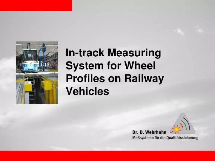
In-track Measuring System for Wheel Profiles on Railway Vehicles
Overview • Principle Of Operation Of Point Laser Triangulation Sensor • Scanning Laser • Sheet Of Light Laser • Automatic In-Track Measurement System • Wheel Profie Measurement with Sheet of Light Sensors In-Track • Reference values of the diameter measurement • Video • Measurement report • Profil analysis • Functions of the measuring system • Technical data • Mounting dimensions In-Track Measurement System
Principle Of Operation Of Point Laser Triangulation Sensor Measuring Range: 4 - 1500 mm Stand Off: 50 – 1200 mm Bandwidth: up to 50 kHz Detector: CCD or PSD Point laser
Scanning Laser Measuring range: 10- 300 mm Stand Off: up to 600 mm Scanline: up to 300 mm Scanfrequency: 20 Hz
Sheet Of Light Laser Measuring range: 10-300 mm Stand Off: up to 400 mm Scanline: up to 200 mm Scanfrequency: 2000 Hz (depents on the resolution)
Automatic In-Track Measurement System Wheel Profile measurement Diameter measurement Profile recording Calculation of flange height, flange thickness, back to back, …. Automatic train detection by transponder Drive through speed 3…10 km/h
Wheel Profie Measurement with Sheet of Light Sensors In-Track High speed measurement Measuring accuracy wheel profile <+/- 0.2 mm Measuring accuracy wheel back distance <+/- 0.5 mm
Reference values of the diameter measurement • 6 OPTIMESS M CCD sensors worked during passing • 400 synchronous measurements per sensor (2400 measurement points) • Measurement range 60mm • afterward calculation of the measurement data diameter
Functions of the measuring system (1) • Measurement of wheel profile and diameter in passing at 3 – 10 km/h • Identification of the vehicle by the transmitted transponder number • Automatic assignment of the measured data to the vehicle and wheel set • Determination of the wheel flange widths B, wheel flange heights H, qR-dimensions and wheel back distances • Automatic direction detection and pickup of measured data in forward direction only • Saving of all measured data in the integrated database • Graphic display of the vehicle’s measured data • Checking of a max. 3 limit values of the wheel flange dimensions depending on the wheel back distance and wear condition • Saving of the vehicle parameters for 30 vehicle types, can be called by the transponder number
Functions of the measuring system (2) • Detection of over rolling of the wheel flange summits on the inside of the wheel • Trend analyses and wear forecasts for wheel set, vehicle, fleet • Function for calibrating and testing the system • Interface for transferring the data to SAP • Display and output whether a vehicle needs to be overhauled.
Technical data • Speed range 3 – 10 km/h • Measuring accuracy wheel profile <+/- 0.2 mm • Measuring accuracy diameter <+/- 1 mm • Measuring accuracy wheel back distance <+/- 0.5 mm • Operating temperature -20 .. 45 °C • Power supply 230 V • Compressed air 6 bar