Download
1 / 20
200 likes | 207 Views
This presentation discusses the high-gradient performance and breakdown measurements in the LINAC4 RFQ. It covers the technical specifications, DAQ modification, and preliminary study of the breakdown phenomenon in the RFQ. The goal is to transfer knowledge from high-gradient CLIC acceleration structures to the RFQ.

E N D
Breakdown measurements in the LINAC4 RFQ Anna Vnuchenko CSIC / IFIC – Instituto de Fisica Corpuscular (CSIC-UV) BE RF and BE ABP group, CERN • CLIC Workshop 2019, CERN
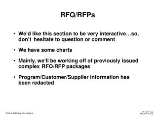
Outline • Introduction • Review of the 352 MHz RFQ of Linac 4, CERN • Technical specification of the RFQ • DAQ modification • Preliminary study of Breakdown phenomenon in the RFQ • High-gradient performance of the structure • Conclusions and next steps • CLIC Workshop 2019
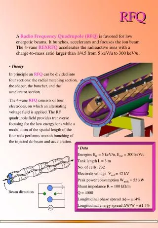
Motivation Transfer Knowledge from High-Gradient CLIC acceleration structure to the RFQ. CLIC structure, 12 GHz 180 ns, 120 MV/m RFQ Linac 4, 352.2 MHz 600 µs, 34 MV/m Investigate high-field limits in new parameter ranges, in particular at low frequency and a very different field profile. Study the high gradient performance of the RFQ and define limiting factors. Achieve a high surface electric field in the RFQ while minimising risk of sparking and damage. Use knowledge gained to optimize the design of structures. Future project: Redesign and potential build of a Linac 4 spare RFQ on a maximum surface field (about 50 MV/m): 352 MHz, 600 µs pulse length H- beam. • CLIC Workshop 2019
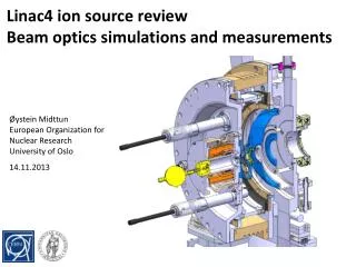
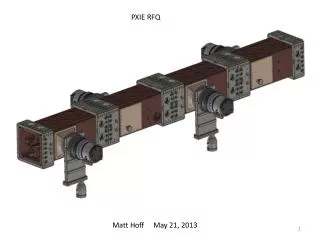
The RFQ LINAC 4: Technical specification • 4-vane structure with 2 brazing steps; • 3 elementary modules of 1 m; • Operation: 480 kW, 750 us, 1.2 Hz; Ion Source • CLIC Workshop 2019
Benefits of a high field for the RFQ High peak fields increase the RFQ performance in areas of: • but also have the effect of: • Increased probability of sparking; • More RF power required ; • Tighter machining and alignment tolerances. • Higher acceptance (larger emittance beams); • Greater space charge capability; • Accept heavy ions with lower charge state; • Shorter RFQ; Comparison of measured emittance (yellow) and RFQ acceptance (pink). Average current: 40 mA The main problem: the expected transmission through the RFQ is 75%. (PARMTEQ + TOUTATIS) • CLIC Workshop 2019
High gradient optimization • Solution: maximize the field on the vane-tip • take into account the proportion between transverse acceptance and efficiency of acceleration (modulation factor); • minimise a transverse radius of curvature. * enhancement factor Field enhancement factor vs modulation for r0=3.256 mm, pho/ro=0.89 and varying cell length L (mm) Beam goes into the paper in between the 4 vane-tips 2R0 = average distance between opposite vanes rho : Transverse radius of curvature of the vane-tip. DATA from V2TERM(CHARGE3D) • CLIC Workshop 2019
Identification of the BD in RF accelerating structures • BD diagnostics: • RF signals: • Directional coupler: incident and reflected signals • Pickup: signal of field in the RFQ cavity • Oscilloscope : additional record the signals • Vacuum diagnostic signals (vacuum gauges). • Field-emitted current(Faraday cups, BLMs). Reflected RF Incident RF Transmitted RF Incident RF Reflected RF BD Beam Axis Emitted Current Transmitted RF (Pickups) Vacuum Signals • BD position can be resolved using timing of RFpulses. • CLIC Workshop 2019
Acquisition system of RFQ Linac 4 DAQ of the RFQ based LabVIEW software: • 16 signal from pick ups; • Detect instability or BDs (depend on pulse flatness); • Record the average value of the pick up signals. 2. DAQ of LINAC 4: • RF signals are recorded in TIMBER: forward, reflected (DC), • Vacuum signal. • Signals are not synchronized in time. • CLIC Workshop 2019
RF power signals measurement: Normal RF signals: RF signals of BD: • CLIC Workshop 2019
RF parameters measurement When the RF pulse turned off, the signals decayed to 0 in the form of exponential decay. , The RF signals: The effectivereflectedvoltage: 1) thedirect-reflectedwave from the coupler, 2) the radiated wave from the cavity. REF Pick up • Measured REF signal is overcoupled: • power rise time is about 20 us • filling time is about 10 us HG18: Wenbo Ye, Tsinghua Univ. QL calculates bythe slope of the decay of the cavity power when the pulse is over. QL = −ω0/2k, wherethe slope k = −1/ τ • CLIC Workshop 2019
RF parameters measurement Normal pulses (theoretical value): f = 352.2 MHz β = 1.5926 Unloaded Q-factor ≈6772 • BD pulse: • τ = 1 – 2 us, • Loaded Q-factor ≈ 1100 – 3085 • => Q-factor = 2850 - 5700 • Decay time of the stored energy varied from event to event • Quality factor of the structure at BD is twice smaller compare to normal operating regime. • CLIC Workshop 2019
RF parameters measurement Normal: Pick up BD: Pick up 1 BD: Pick up 5 f = 352.2 MHz • Non Resonant frequencies appear during BD • Radiative value is driving with BD present Pick up 1 and 5 located at the same vane, E field direction from 5 to 1: BD occurred in front of the structure (beam direction) Beam RF • CLIC Workshop 2019
Operation history plot of the RFQ at LINAC 4 Cumulative number of BDs as a function of cumulative number of rf power pulses for t = 700 us, BDR = 3.85 E-5 bpp • Non linear increasing number on BD (clusters): • CLIC Workshop 2019
BD positioning in pulse LLRF changes: RF immediately come back to previous value after BD • CLIC Workshop 2019
BD positioning in pulse • 53% all BDs happened at over ramped part of pulse • CLIC Workshop 2019
BD rate analysis • BDR used to predict the behaviour of the structure and the determine nominal operating parameters. • There are lower power at the cavity during operation with beam. • No big difference without beam at higher power. • Not enough statistics to made conclusions. • CLIC Workshop 2019
BD study of RFQ L4 Example 1: The predominant form of breakdown in the structure (60 %) 3 Vanes: 4 2 1 RFQ with 16 probes Signals from 16 pickups FayaWang, Chris Adolphsen, Phys. Rev. ST Accel. Beams 12, 2009 When RF BDs occur, the cavity divided to 2 sections: power continue to flow into section with coupler. • CLIC Workshop 2019
BD study of RFQ L4 BD study of RFQ L4 Example 2: High Radiative wave at 2 and 4 vane (20%) 3 4 2 1 Vanes: 5 6 9 10 11 12 7 8 RF Signals from 16 pickups RFQ with 16 probes • BD occurred in central part of the structure: front of the RF port • CLIC Workshop 2019
Conclusions: • The high gradient experience of CLIC cannot directly scale to the RFQ because the operating regime is completely different: pulse length, repetition frequency and way of filling (standing wave structure + ion source). • The first study of BD phenomena was performed in the RFQ Linac 4. • Q-factor at BD is lower compared to the value during normal operation. • Non resonant frequency occurred at BD. • Preliminary analyse show that the main number of BD happened after full filling of the cavity. Future work: • Continue breakdownlocationanalysis. • Implement CLIC conditioning algorithm to the new RFQs. • CLIC Workshop 2019
Thank you for your attention! CLIC Workshop, 21/01/2019