Download
1 / 17
170 likes | 330 Views
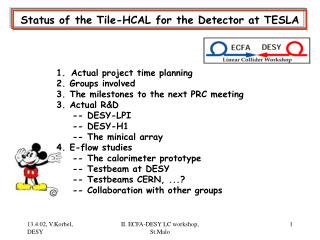
9. 3/5/02. The HCAL Calorimeter for the TESLA Detector. HCAL, a tool for Energy flow measurement : calorimeter and trackers used to measure energy of particles in jets; this considerably improves the measurement of final states. The trackers are used:

E N D
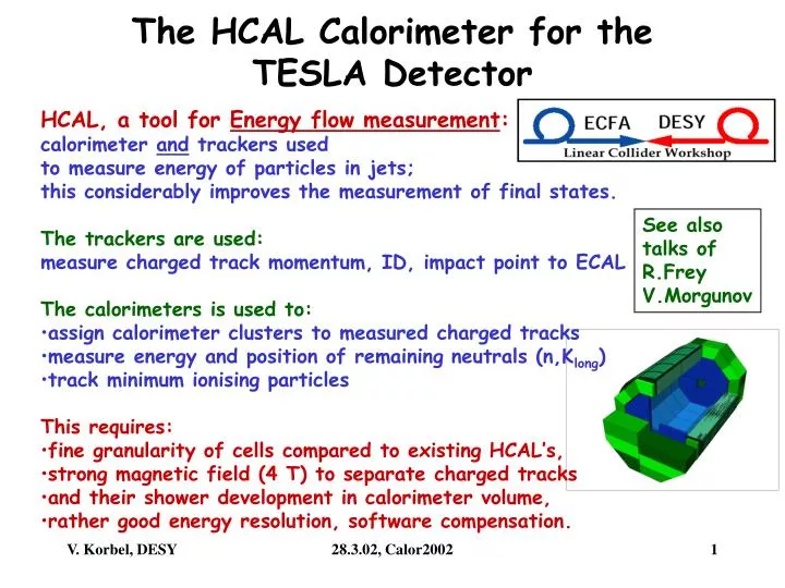
9 3/5/02 The HCAL Calorimeter for the TESLA Detector • HCAL, a tool for Energy flow measurement: • calorimeter and trackers used • to measure energy of particles in jets; • this considerably improves the measurement of final states. • The trackers are used: • measure charged track momentum, ID, impact point to ECAL • The calorimeters is used to: • assign calorimeter clusters to measured charged tracks • measure energy and position of remaining neutrals (n,Klong) • track minimum ionising particles • This requires: • fine granularity of cells compared to existing HCAL’s, • strong magnetic field (4 T) to separate charged tracks • and their shower development in calorimeter volume, • rather good energy resolution, software compensation. See also talks of R.Frey V.Morgunov 28.3.02, Calor2002
TESLA Detector, cross section • The calorimeter family: • The barrel, from 90 to ~45 • ECAL (1.1l) • HCAL (1.1-5.6l) • coil (5.6-6.4l, dead material) • instrumented iron (6.4-15l) • The end caps, from ~45 to ~5 • ECAL (1,1l) • HCAL (1,1-6.5l) • instrumented pole tip (6.5-12l) • instrumented iron yoke(12-18l) • The forward calorimeter, < ~5 • (for e only) • large angle tagger (LAT) • luminosity monitor (LCAL Map of the calorimeter landscape: hermeticity and containment 28.3.02, Calor2002
TESLA Detector, cross section, more details • Energy flow measurement: • additional information from: • vertex detector • intermediate trackers • TPC • >> • vertex of event • momentum of charged tracks • particle identification • particle impact point at ECAL • for concept/design of ECAL • see talk of H. Videau • also essential: • minimal cracks • no dead material in volume • no material in front 28.3.02, Calor2002
Cut across the barrel calorimeter • Sandwich layers: • 5 mm scintillator • 1.5 mm gap • for fibre RO and • reflector foil • 20mm Fe absorber • 1 s/w layer • =1.15 X0, 0.12 l • these parameters • define • energy resolution 16 tapered modules in 8 x symmetry 28.3.02, Calor2002
The layer structure of the HCAL • HCAL granularity to be optimised • for E-Flow reconstruction of jet energies, • ~angles • and jet-jet masses. • sandwich layers, lamination in: • 38 in barrel, 45 in end caps, • add. 4 in pole tips of end-caps • with scintillator tiles: ~ 800 000 tiles • sizes:~5x5......~16x16 cm2 • cells: ~ 160 000 cells • 9 (10) cell layers in barrel (end cap), • grouped from 3,3,3,4,4,4,5,5,7 • (3,3,3,4,4,4,5,5,7,7) s/w layers • cell volumes: • (0.22l)2 x0.36l .... (0.71l)2 x0.84l • (1.6 RMoliere)2 x 3.5 X0 ...(5 RMoliere)2 x 8 X0 28.3.02, Calor2002
The calorimeter modules No explicit pointing tower geometry • End cap HCAL • 1 quadrant • assembled to wheel • 4 different cell depth • front side ring surrounding • end cap ECAL One of 32 Barrel HCAL modules 4 different cell depth • End cap cell arrangement: • cell sizes grow with distance • to beam • projective at small polar angle • Barrel cell arrangement is • projective in azimuth, • non projective in polar angle 28.3.02, Calor2002
The complete hermetic calorimeter • Containment: • barrel: 1.1+4.5 =5.6 l • end caps 1.1+5.4+5.5 =12 l • Beam hole is closed by the mask • tungsten (electromagnetic shield) • graphite absorbers (neutron shield) 28.3.02, Calor2002
Concept of tile plate read out Problematic are the small scintillator tile sizes to be read out 1. layer Example of a photo-detector for fibre RO, 32 pixel APD array, HAMAMATSU These figures show the original concept as described in the TESLA-TDR. So far detector concept and design, now the R&D studies 28.3.02, Calor2002
R&D studies on the tile-WLS fibre system Scintillator light yield R&D Scintillator : uniformity of RO Scintillator : ~6600 m2, costs! • Tile-WLS system: • optimal coupling, • light yield, • uniformity • >>>> 5x5 cm2, than: ...7x7....16x16cm2 tiles Reflector foil: mirror or diffraction, light yield Reflector foil: uniformity of RO Green WLS fibre: attenuation length R&D by: DESY-H1, Prague, LPI + ITEP, Moscow WLS fibre: bending in small radius WLS fibre: ageing, rad. hardness WLS fibre: fibre end mirroring clear RO fibre: attenuation length 28.3.02, Calor2002
Scintillator/WLS fibre coupling Fibre end polished, open Tyvek coating of tile, air gap contact tile/WLS Look for cheaper scintillator from Russia, with similar performance! 28.3.02, Calor2002
Search for optimal WLS-Fibre arrangement • 10 different configurations studied • fibre end polished, no reflector • air gap contact tile/WLS • Tyvek reflector on tile • tile irradiated with • collimated Ru106 source, s ~ 2cm, • simple current measurement for LY 28.3.02, Calor2002
Uniformity scan for optimal WLS-Fibre couplings 10 configurations studied: s source =1.95 mm, best LY: 1/4 circle fibre RO in groove best uniformity: straight fibre RO outside tile All tiles: 5x5x0.5 cm3 LY and uniformity normalised to diagonal groove RO 28.3.02, Calor2002
Light yield and uniformity for larger tiles Tile a x a (cm2) 5 x 5 10 x 10 15 x 15 LY (nA) 105 +- 6 60 +- 4 39 +- 6 Relative LY 2.4 +- 0.4 1.5 +- 0.3 1 Photo e- 6.5+-0.4 *) 4 +- 0.2 2.5 +- 0.2 LY / photo e- (nA) 16 +- 1.7 15 +- 1.4 16 +- 2.8 Tile (cm2) 5 x 5 10 x 10 15 x 15 Uniformity (%) 4.0 – 6.0 5.0 – 6.5 4.0 – 5.5 light yield uniformity • improve LY for large tiles with WLS loops • signal of large cells will be increased by more sampling layers • actual established LY is ~20 pe/cell/MIP • uniformity is ok, needs confirmation by simulation studies. 28.3.02, Calor2002
A small pre-prototype : the „minical“-array • Assembled with up to • 27 scintillator layers: • 165 scintillator tiles of: • 5x5 cm2 >> 45 cells • 10x10 cm2 >> 8 cells • 20x20 cm2 >> 2 cells • read out by WLS fibres to • photo-detectors: • 16 small PM’s • 3x16 MA-PM’s, • 1x32 APD array • later: • Si-PM’s (MEPHI, Moscow) Track cambers? Cell structure Tile and S/w structure Aim of this device is study of: stability, ageing and calibration with MIP’s 28.3.02, Calor2002
HCAL prototype for E-flow studies • Required volume ~ 1 m3 • ~ 800-1200 calorimeter cells • Fe-structure can accept • analogue • or digital HCAL 10 GeV pions 100 cm Leakage detector needed! 100 GeV pions 28.3.02, Calor2002
Summary • CDR >> TDR (2001) considerable improvement in design • straight fibre RO of smallest cells • >> ~20 p.e. for calibration with MIPs • work on further improvement in light yield • lateral cell response uniformity seems ok, • but needs confirmation by simulation studies. • studies are underway for cell size optimisation (E-flow) • minical-prototype is in operation • prototype tests at CERN envisaged for 2004 28.3.02, Calor2002
Minical Here we are 2002 Outlook Concept, design studies, R&D, prototype to be built >2004 Approved, final concept 2005 ? design Detector ready for first e-e interactions: 2012 ? 28.3.02, Calor2002