Download
1 / 126
1.27k likes | 1.49k Views
Systolic Ring : Scalable Structure. Switch. Switch. Switch. Switch. Systolic Ring. Dnode Sequencer. layer 1. Based on a coarse-grained configurable PE Circular datapaths C: # of layers C = 4 N: # of Dnodes per layer N = 2 S: # of Rings s = 1 Control Units (sequencer)

E N D
Switch Switch Switch Switch SystolicRing Dnode Sequencer layer 1 • Based on a coarse-grained • configurable PE • Circular datapaths • C: # of layersC = 4 • N: # of Dnodes per layer • N = 2 • S: # of Rings s = 1 • Control Units (sequencer) • Local Dnode unit • Local Ring unit • Global unit Dnode Dnode layer 4 Local Ring Sequencer Dnode Dnode Dnode Dnode layer 2 Dnode Dnode layer 3
NPE: # of processing elements (PE) Nc: # of PE configurable per cycle Fe: operating frequency Fc configuration frequency Characterizes the Dynamism # of cycles to (re)configure the whole architecture Amount of data to compute between 2 configurations Configuration Configuration Memory Memory inst inst inst inst inst inst inst inst … … inst inst 0 0 1 1 2 2 3 3 n n Sequencer Sequencer Processing Elements Processing Elements N . Fe = PE R PE PE PE PE PE PE PE PE … … PE PE Sequencing Sequencing Unit Unit Nc . Fc Interconnection Interconnection Routing Routing Remanence Fc Fe
Configuration Configuration Memory Memory inst inst inst inst inst inst inst inst … … inst inst 0 0 1 1 2 2 3 3 n n Sequencer Sequencer N Processing Elements Processing Elements = PE OD ( N ) PE A ( N ) PE PE PE PE PE PE PE PE … … PE PE Sequencing Sequencing Unit Unit PE Interconnection Interconnection Routing Routing Operative Density NPE: # of PE A: Core Area (relative unit ²) Area can be expressed as a function of NPE
Remanence formalisation • # of layers : C = 8 • # of Dnode per layer : N = 2 • 1 Systolic Ring: S = 1 layer 1 layer 2 layer 8 layer 3 = R ( N ) k . N PE PE k= C/N REMANENCE REMANENCE layer 7 layer 4 40 40 35 35 30 30 k = 8 k = 8 25 25 k = 4 k = 4 20 20 k = 2 k = 2 layer 6 layer 5 k = 1 k = 1 15 15 10 10 5 5 0 0 # # Dnodes Dnodes 0 0 20 20 40 40 60 60 80 80 100 100 120 120 140 140 160 160 180 180
Architectural model Characterization • # of layers : 4 (C = 4) • # of Dnode per layer : 2 (N = 2) • 4 Systolic Ring (S = 4) • Control Units • Local Dnode unit • Local Ring unit • Global unit Global Sequencer Local Ring Sequencer Local Ring Sequencer Local Ring Sequencer Local Ring Sequencer • www.qstech.com
Best OD and remanence Design Space Worst interconnect resources and processing power
Worst OD and remanence Best interconnect resources and processing power Design Space
Name Type NPE Nc F (MHz) R ARDOISE Fine Grain RA 2304 0.14 33 16457 MorphoSys Coarse Grain RA 128 16 100 8 Systolic Ring Coarse Grain RA 24 4 200 6 DART Coarse Grain RA 24 4 130 6 TMS320C62 DSP VLIW 8 8 300 1 Comparisons of RA • Only 1 cycle to (re)configure the DSP • Few cycles to (re)configure coarse grain RA (8) • Many cycles to (re)configure fine grain RA Pascal BENOIT
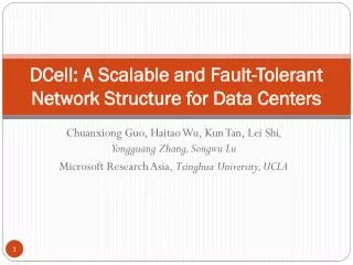
Modeling and Implementation ofNetwork-on-Chip Interconnects • S. Bourduas J.-S. Chenard Z. Zilic • Microelectronics and Computer Systems Lab • Electrical and Computer Engineering • McGill University • October 24, 2006
Network-on-Chip (NoC) • Communication is achieved by connecting switches together to form a network topology: • Offers much greater scalability. • parallelism: multiple components can send data simultaneously • energy efficient: point-to-point connections require less energy than a bus. • Global synchronization is no longer needed.
NoC Design Considerations (I) • There are several popular topologies: • 2D Mesh (most popular). • Torus (rings) • Tree (fat-tree, butterfly fat-tree) • The on-chip interconnection network will soon be a limiting • factor for performance and energy consumption: • has been reported to account for over 50% of the total energy requirement! • The interconnect should consume the fewest resources possible and should be: • area efficient: switches should be as small (simple) as possible. • energy efficient: related to area efficiency • fast: simple routing algorithms should be used.
NoC Design Considerations (II) • Need to consider how well a topology maps to 2 dimensions: N-Dimensional structures such as 3D Meshes are difficult efficiently to map to a 2D space. • Routing in N dimensions: Switches have a higher number of input/output ports resulting in increased complexity. • Prefer 2D interconnect topologies.
Analysis of Hierarchical Rings • High-Level Model: • A high-level SystemC simulation model was used to model a hierarchical ring interconnect and to explore the effect of dynamic frequency scaling. • Low-Level RTL: • A VHDL implementation was synthesized in order to determine the physical characteristics of the interconnect.
SystemC Simulation Model • We evaluated a multiprocessor system-on-chip (SoC): • Hierarchical ring interconnect which uses unidirectional rings. • 16 Processing elements (ARM processors, Memory, DMA, AMBA • Bus). • Energy model was integrated into the interconnect model. • Enabled design space exploration. • Enabled application of dynamic power optimization to interconnect. • Simulation results showed that significant energy savings could be achieved with little impact on performance.
VHDL Implementation of Hierarchical Ring Interconnect • We evaluated a RTL-Level implementation of a hierarchical ring interconnect for Network-on-Chip (NoC) multi-processors: • Stochastic driven testbenches were used to study the performance characteristics of the interconnect. • Synthesis results showed that hierarchical-rings compare favorably to more common architectures such as the 2D-Mesh.
Motivation For Using Hierarchical Rings • Relatively simple switching logic reduces the complexity at each node resulting in reduced buffer, area and energy requirements. • Low latency since packets are forwarded in 1 clock cycle. • Packets will always arrive in-order at the destination. • Broadcast and Multicast packets are efficiently implemented. • Hierarchical rings can be partitioned into independent clock domains.
Target Applications • Multimedia applications often involve a series of processing steps where data is processed in a pipelined fashion. • sequential data processing is efficient because multiple simultaneous transfers between adjacent nodes is inherently supported. • For real-time applications as well as multimedia applications, low latencies, guaranteed delivery and in-order arrival are critical.
Routing • Packets are bit-parallel signals that are forwarded in 1 clock cycle (phit/flit = 58 bits). • Addresses are one-hot encoded: • Ring 0: 0001 • Processing Element 2: 0100 • Masks are used to determine where to route packets: • simple and fast. • one-hot encoding enables efficient implementation of multicast/broadcast. • Unidirectional rings means that only one path exists between nodes and packets are guaranteed to arrive in-order.
Flow Control • A backpressure mechanism is used to handle congestion and to avoid packet loss: • When a input fifo of any of the RIs is almost full, all RIs are • prevented from injecting new packets. • When a downwards FIFO in one of the IRIs is almost full, no more packets are put onto the global ring. • When the backpressure mechanism is in effect, packets that are already on the rings will continue to be forwarded, thus ensuring that the packets will reach their destinations and that deadlock cannot occur.
Processing Element A processing element (PE) consists of: Leon3 processor core, including cache.memory controller and memory. AMBA bus and arbiter Station-Ring Interface (SRI). The station-ring interface (SRI) has been implemented to support direct memory access (DMA) to memory.
Energy Model of the Interconnect • Main contributors to energy consumption are: • Ring interfaces (buffers and control logic. • Point-to-point wire connections between adjacent nodes. • Energy characteristics of the ring interfaces were obtained by using Synopsys Design/Power Compiler.
Energy Optimization • Energy optimization is accomplished by varying the ring speeds based on buffer occupancies. • Slow down the rings when buffers are nearly empty. • Speed up rings when buffers start to get full. • Energy consumption of the ring interface • can be expressed as: Where kf is the divisor used to lengthen or shorten the clock period of the rings.
Design Space Exploration • Burst length : The burst length is the maximum number of words a station can send with a DMA operation. • High burst length ! more backpressure signals. • Low burst length ! low network utilization. • Memory access time : Explore the effect of memory access latency on system performance. • Select least expensive component that satisfies performance constraints. • FIFO Depth : FIFO size affects area, cost, energy consumption and performance. • FIFO size greatly affects performance and cost.
FIFO Depth • Contrary to expectation, increasing FIFO depth does not result in significant • performance increase: • 1 Matrix transposition program is bursty. • 2 Interconnect is able to keep up with bandwidthdemands with smaller FIFOs.
Energy Optimization • Each ring is divided into a separate clock domain. • The speed of each ring is adjusted dynamically depending on the buffer occupancies: • Speed up when FIFOs are full. • Slow down when FIFOs are empty. • Local/Central constant divisors set the maximum ring speed: • Divisor of 2 means means that ring speed is capped at: • fcapped = fmax / 2 • Simulations results for varying divisor constants were compared (see next slide).
Effect of Varying Ring Speeds • Varying ring speeds: has small impact on execution time and achieves substantial energy reduction. • Dynamic optmization reduces power consumption by 30 − 70% over the unoptimized case.
SystemC NoC Topology Exploration Platform • Implementing a NoC is time consuming and difficult: • Need a mechanism to quickly model and evaluate different topologies. • Implementing in low-level RTL is time consuming and difficult: Leverage existing SystemC model to generate RTL automatically.
Motivation • Our existing hierarchical-ring simulator was not designed with reusability/extensibility in mind. • in/out ports were connected in an ad-hoc manner which was not easy to modify. • Connecting components together in VHDL in order to form a topology must be done ‘by hand’ and is tedious and time consuming. • Easier to construct a topology in SystemC and then generate the VHDL code automatically.
architectures applications methodologies The Design Triangle
Top-down 접근방법에는 시스템 레벨의 모듈을 합성하는 방법(COSYMA, SpecC)과 플랫폼 기반에서의 디자인 방법(VCC, GSRC, Coware)이 있다. • Bottom-up설계 방식에는 컴퍼넌트 기반 설계 방법이 있다. 이 방법은 여러 컴퍼넌트를 이용해 특수 목적의 아키텍쳐와 커뮤니케이션 API를 구성하게 하는 것이다. 이 방법의 핵심은 컴퍼넌트의 상호연결을 추상 레벨에서 수행하는 것이다.
IMEC의 Roses (설계 환경) : Component-based design automation tools for MP-SoCs
IMEC의 Roses (설계 자동화 도구)는 통신 코프로세서, 랩퍼, 디바이스 드라이버, 운영 시스템, API를 모두 자동 생성한다. 각각의 타겟 프로세서를 위해 최적화되고 미리 구성된 운영 시스템을 생성한다. API, 통신 서비스, 디바이스 드라이버로 구성된 라이브러리를 이용하여 생성된 운영 시스템은 다음의 세가지 서비스를 제공한다. 1) 통신: 예)FIFO 2) I/O: 예)AMBA bus 드라이버 3) 메모리: 예) 공유 메모리 공간.
Two-layer hardware-dependent software • •Lack of SW portability: 소프트웨어가 하드웨어 종속적이기 때문에 다른 MP-SoC 구조에 바로 적용할 수 없고, 소프트웨어의 수정이 필요하다. 이 수정시간이 개발 시간을 지연시킨다. •Lack of early SW validation: 개발 시 하드웨어가 구현된 상태에서 소프트웨어 확인이 가능하므로, 개발 시간이 길어진다. 해결 방안: 하드웨어와 응용소프트웨어 중간에 인터페이스 층(HAL: hardware abstraction layer)을 두는 것이다. 하드웨어에 따라 인터페이스 층만 달라지고 응용 프로그램은 수정 없이 재사용이 가능하게 되는 것이다.
SW portability in architecture exploration L. Gheorghe, G. Nicolescu, “MP SoCs including optical interconnect: technological progresses and challenges for CAD tools design” IWSOC 2005, 20-24 pp. 546 - 551 July 2005
A system level processor/communication co-exploration methodology K. Lahiri, A. Raghunathan, S. Dey “Efficient Exploration of the SoC Communication Architecture Design Space” in Proc ICCAD 2000
하드웨어 모델= HDL 모델 • Seamless CVE 는 100개 이상의 CPU와 DSP의 모델을 PSP(Processor Support Package)형태로 제공한다. PSP는 ISM(instruction-set model)과 BIM(bus-inteface model)를 포함하고 있다. [그림 2.11]에서 이를 도식화하고 있다. ISM은 소프트웨어의 명령어를 시뮬레이션 하기 위한 모델이다. BIM은 실제로 ISM에 의해 프로세서 외부로 나오는 신호를 시뮬레이션 하기 위한 모델이다. 예를 들어 ARM을 이용해 메모리에 값을 쓴다고 가정했을 때 ISM은 이 동작을 수행하는 명령어를 해석하고, 실제 어드레스가 BIM을 통해서 출력되게 된다. 즉, 프로세서 모델에서 ISM은 소프트웨어 모델이고, BIM은 하드웨어 모델이라고 볼 수 있다. BIM을 HDL코드에 삽입하여 원하는 하드웨어를 구성하여 하드웨어 시뮬레이터(ModelSim)에서 하드웨어 시뮬레이션이 수행되고, 소프트웨어 시뮬레이터에서 ISM을 통해 소프트웨어 시뮬레이션을 가능하게 한다. • 심리스에서 시뮬레이션 최적화를 위해서는 특별한 메모리 모델이 필요하다. 이 메모리 모델은 심리스 자체에서 지원하는 메모리 모델과 Denali사의 메모리 모델이 있다.
소프트웨어 • 소프트웨어 시뮬레이터 즉, ISS(Instruction-set Simulator)를 이용해 소프트웨어 시뮬레이션이 수행된다. 소프트웨어는 각 각의 프로세서에 해당하는 cross-compiler를 이용하여 ELF파일을 생성하여 각 프로세서에 ELF(Executable and Linkable Format)파일을 로딩하여 실행하게 된다. • 심리스에는 ARM을 위한 디버거로서 X ray 디버거와 ArmSD 디버거가있다. • ArmSD 디버거는 텍스트환경이며, Xray 디버거는 그래픽 환경에서의 디버거이다. 이 디버거들은 ISS의 역할은 하며, 디버깅 환경을 제공한다.
버스(AMBA 버스) • •AHB single-layer: AHB 싱글 레이어의 단점은 다수의 마스터와 다수의 슬레이브가 있을 때 하나의 마스터가 하나의 슬레이브에 접근되었을 때, 다른 슬레이브로 접근하고자 하는 다른 마스터의 접근은 허용되지 않는다. 즉 다수 마스터와 다수 슬레이브의 동시 접근이 불가능하여 버스의 병목 현상이 발생된다. • AHB multi-layer: single-layer의 확장된 구조로서 single-layer의 단점인 동시 접근성을 허용한 버스 구조이다. 이 버스 구조에 의해 버스에서의 병목 현상을 줄일 수 있다. [그림 1.12]는 간단한 AHB multi-layer구조의 시스템이다.
Simple AHB multi-layer System 각각의 마스터는 하나의 layer를 구성하고 있으며, Decoder로 Mux를 컨트롤하여 통신하고자하는 슬레이브로 연결된다.
MP-SOC OS • MP-SOC에서 각각의 OS는 각 프로세서 별로 독립적으로 실행되며, 각각의 작업은 프로세서에 맞게 할당된다. 작업은 여러 작업들 가운데 parallel로 또는 serial로 수행된다. • Process Management • Process의 생성과 소멸 • Process간의 통신 • Process의 scheduling • Memory Management • Memory 자원 관리 • Process에 memory 할당 • File Management • File과 Directory의 생성과 소멸 • I/O System Management • Device Driver Interface • Hardware Device Control