Download
1 / 37
370 likes | 533 Views
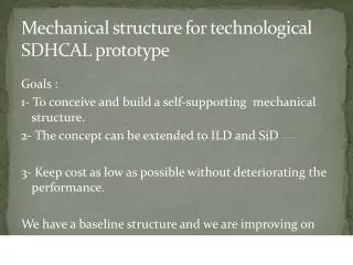
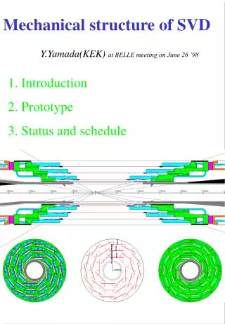
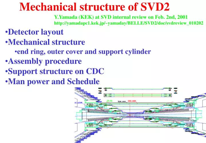
Mechanical structure of SVD2. Y.Yamada (KEK) at SVD internal review on Feb. 2nd, 2001 http://yamadapc1.kek.jp/~yamaday/BELLE/SVD2/doc/svdreview_010202. Detector layout Mechanical structure end ring, outer cover and support cylinder Assembly procedure Support structure on CDC

E N D
Mechanical structure of SVD2 Y.Yamada (KEK) at SVD internal review on Feb. 2nd, 2001 http://yamadapc1.kek.jp/~yamaday/BELLE/SVD2/doc/svdreview_010202 • Detector layout • Mechanical structure • end ring, outer cover and support cylinder • Assembly procedure • Support structure on CDC • Man power and Schedule
Detector layout (Radii are 30, 45 and 60 mm in SVD1.)
Inner radius • Number of layers depends on beampipe radius • Routbp = Rinbp + dRbp(=1.5 mm ) • dRbp = 0.5 mm (inner Be) + 0.5 mm (PF200) + 0.25 mm(outer Be) + 0.25 mm (gold) • RinSVD = Routbp+1 mm (11 mrad tilting) + 1 mm (production tolerance) + 1 mm (gap) • R1st layerSVD < 15 mm for no dead region in • Rinbp < 10.5 mm : five layers • Rinbp > 10.5 mm : four layers
Outer radius • CDC : cathode part small cell chamber • CDC inner radius : R = 77 mm 102 mm • SVD • outer cover : • R = 75 mm 100 mm • outermost layer : • R = 60 mm 90 mm
Design features • Same concept with SVD1 • end rings for ladders • outer cover and support cylinder for main structure • clam shell division at assembly with beam pipe • New features • Full acceptance of BELLE : 17º < q < 150º (23º < q < 140º in SVD1) • not straight ladder using flex circuit • super-layer structure for first and second layer in five layer design • CFRP for end ring • DSSD is cooled down to 15 degree C • no inner cover • replaceable inner end ring • more number of ladders : 32 (SVD1) 60(SVD2 5 layer) • longer ladder : 37cm (SVD1 3rd layer) 65 cm (SVD2 5th layer) • Minimum number of variations on ladder parts • three (narrow, normal and wide) DSSDs, two (normal and wide) hybrids, • narrow one-DSSD half ladders for 1st layer, • normal one-DSSD, two-DSSD and three-DSSD half ladders for 2nd/3rd/4th layer, • wide three-DSSD half ladders for for 5th layer
Mechanical structure of SVD2 • Four or Five layers of DSSD ladders are supported by the end rings • which is made of Aluminum and CFRP, • Forward and backward end rings are connected by the outer cover • which is made of 0.5mm-t CFRP, • end rings and outer cover are supported by forward and backward • support cylinders which is made of 2.5mm-t CFRP, • support cylindersare supported by the end plates of CDC.
Structure of SVD1 DSSD ladder end ring outer cover beam pipe support cylinder
Outer cover and support cylinder stiff cylinder : EI = 1 x 10⁴ Nm2 SVD1 outer cover (R=7.5cm, 1.5 mm-t) support cylinder (2.5mm-t) • CFRP • Mitsubishi-chemical Co. • E = 200 GPa • CTE = 1x10⁻⁶ m/m/°K • 220 W/m/°K SVD1 SVD1
FEM analysis (SVD1) Gravitational sag is ~ 6 microns
End ring • Backward end ring • inner ring for 2nd layer • outer rings for 3rd/4th/5th layer • Forward end ring • inner ring for 1st/2nd super-layer • outer rings for 3rd/4th/5th layer
Forward end rings • outer ring • Al ring • for 3rd/4th/5th layer • CFRP cone • Flange for support • cooling tube • inner ring • Al ring for • 1st/2nd super-layer • (or 2nd layer) • CFRP cone • Flange for support • cooling tube
Forward end rings super layer for 1st/2nd layer 3rd layer 4th layer 5th layer
Backward end rings 5th layer 4th layer 3rd layer 2nd layer
Support flange (forward) CDC endplate side end ring side
Thermal property • At start of operation (or a experiment) • Si DSSD : 0.65 m 3 ppm/° 10 ° ~ 20 mm • CFRP Outer cover : 0.7 m 1 ppm/° 15 ° ~ +10 mm • Al end ring : 0.02 m 24 ppm/° 15 ° ~ 7 mm • should be absorbed by sliding mechanism of ladder Temperature control system during operation was installed last summer. temperature of heat sink Before control : ±3.5° after control : ±1.0° • No deformation • in a experiment time (hours)
Ladder support scheme • ladder (hybrid) is fixed on end ring surfaces • fixed rigidly on backward end ring • fixed on forward end ring with sliding mechanism • using precisely (±10 mm) machined pins and holes 2.0 mm- pin in 3.5 mm- hole in heatsink with special spring 3.5 mm- pin in 3.5 mm- hole in heatsink
ladder support in SVD1 • backward hybrid is aligned by • 5 mm brass pin • 5 mm hole in heatsink • 5 mm hole in end ring. 5 mm pin 5 mm hole SVD1 5 mm hole SVD1 • Forward hybrid is aligned by • 3 mm brass pin • 5 mm hole in heatsink with special spring • 3 mm hole in end ring • allow sliding of ladder • in Z without R-f motion M3 screw with gull wing spring for fixing hybrid 3 mm pin 3 mm hole 5 mm hole with special spring SVD1 SVD1
Property of ladder sliding (SVD1) • If we push ladder from backward side • sliding occurs around D=20 microns • (or dT=10 °C or f=7kgf). • bowing of ladder is 10 microns • at maximum with the ribs of BN • (1mm thick and 7mm high).
Backward hybrid • backward hybrid is aligned by • 3.5 mm brass pin • 3.5 mm hole in heatsink • 3.5 mm hole in end ring. heatsink M3 screw with gull wing spring for fixing hybrid 3.5 mm diameter brass pin in 3.5 mm hole in end ring and heatsink
Forward hybrid • Forward hybrid is aligned by • 2 mm brass pin • 3.5 mm hole in heatsink with special spring • 2 mm hole in end ring • allow sliding of ladder in Z direction without R-f motion heatsink M3 screw with gull wing spring for fixing hybrid 2 mm diameter brass pin in 2 mm hole in end ring and 3.5 mm hole in heatsink
Assembly procedure • Machining end rings on jig using NC machine • Mounting ladders on end rings • Dividing into two clam shells • Assemble inner and outer end rings with support flange • Assemble two clam shells with support cylinders • and beam pipe
machining of end ring SVD1 1/8 inch Cu tube is glued on end ring with silver epoxy. SVD1 Forward/backward end rings are machined on the jig simultaneously to keep forward/backward surfaces parallel. Accuracy is 10 ~ 20 microns.
mounting ladders SVD1 SVD1 End ring with ladder mount jig on assembly bench SVD1
Final assembly SVD1 SVD1 attach outer covers with temp. supports assemble with support cylinder/beampipe SVD1 SVD1 division into two clam shells
Support structure on CDC SVD is supported at three points on forward/backward flange of CDC independently from heavy beam pipe. · · · diaphragm which allows Z motion only backward forward
Recent modification change of connector on hybrid due to increase of lines (34 51) • thickness increased(1.0 3.2) mm 5 layers = 11 mm • large modification of structure required (not yet done)
Task list in near future • modification due to change of connector (one month) • confirmation of interferences using 3D-CAD • simulation on strength and temperature • prototyping ladders and support structure (three months) • design of support mechanism on CDC including beam pipe • design of assembly tools • .....
Man power and schedule • Design, drawing and assembly : • KEK(Y.Yamada, J.Suzuki, S.Koike, A.Satpathy and others) • Machining : • KEK machine shop and others • Measurement and installation : • KEK, Niigata, Tokyo, Osaka, TIT, NTU and others • Temporary schedule for installation in Aug. 2002 • Prototyping by spring 2001 • Final drawing by summer 2001 • Machining by end of 2001 • Ladder mounting by early 2002 • Final assembly by spring 2002