Download

1 / 13
130 likes | 342 Views
DSP 技术与应用. Section 4 ADSP-2191 Memory. Memory. Primarily Store data and instructions Also used to access memory mapped peripherals 2191s can access External memory if present The 2191 has a linear addressing scheme 0x00 0000 to 0xFF FFFF TOTAL 16M words

E N D
DSP技术与应用 Section 4 ADSP-2191 Memory
Memory • Primarily Store data and instructions • Also used to access memory mapped peripherals • 2191s can access External memory if present • The 2191 has a linear addressing scheme • 0x00 0000 to 0xFF FFFF TOTAL 16M words • Address ranges within this field define memory usage • Internal memory blocks • External Memory • 2191s core access memory via the address/data busses • The DM address bus is 24 bits wide = up to 16M memory locations for data • The PM address bus is 24 bits wide = up to 16M memory locations for data and instructions • The 2191 has two other memory spaces • Boot Memory Space, IO Memory Space
Memory Architecture • Memory architecture supports instruction access, data access, and memory mapped peripheral accesses • Supports internal and external memory access • The ADSP-2191 has several memory spaces • Standard memory space • Data, instructions, and memory mapped peripherals • System control register memory space, use • Access specific system registers • IO Memory Space (IOMS) • Internal peripheral control and data registers • Memory mapped peripherals • Boot Memory Space (BMS)
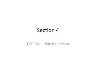
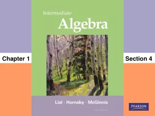
ADSP-2191 Memory Map 23 0 0x00:0000 EXTERNAL MEMORY PROGRAMMABLE START BOUNDARIES (MAX 64KW/PAGE) 24-BIT INTERNAL SRAM (PAGE 0 - DEFAULT) 0x00:7FFF 0x00:8000 16-BIT 0x00:FFFF 0x01:0000 MS0 (PAGES 1-63) 0x40:0000 MS1 (PAGES 64-127) TOTAL MEMORY SPACE 256, 64KW PAGES (16M WORDS) EXTERNAL 16-BIT MEMORY SPACE (254, 64Kx16 PAGES) 0x80:0000 MS2 (PAGES 128-191) 0xC0:0000 MS3 (PAGES 192-254) 0xFE:FFFF 0xFF:0000 INTERNAL ROM (PAGE 255, 64Kx24) 1K BOOTROM 0xFF:03FF 0xFF:0400 63K - RESERVED 0xFF:FFFF
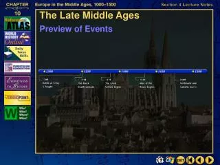
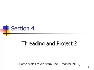
Boot & IO Memory Space IO MEMORY SPACE (/IOMS) EXTERNAL BOOT MEMORY (/BMS) 15 0 15/7 0 INTERNAL (PAGES 0-7) 256 1K PAGES 0x01 0000 64K WORD (BMS) PAGES 1-254 0x00 000 0x07 3FF 0x08 000 EXTERNAL (/IOMS) PAGES 8-255 0xFE FFFF 254 64k pages 0xFF 3FF IOPG8-Bit INSTRUCTION 10-Bit
ADSP-2191 Memory Memory Structure • Internal memory configured for shared core & I/O accesses • I/O processor DMA transfers use ‘cycle stealing’ to access internal memory • Internal memory partitioned into 4 blocks • Supports dual data fetches • Up to two 16-bit data values accessed in single cycle (one over each bus)
The Modified Harvard Architecture Data Memory Address (DAG 1) 16 Bit 24 24 Bit DSP Core Program Memory Address (DAG 2) Instructions fetches are attempted every cycle over the Program Memory bus PM Bus conflicts occur when instruction fetch and PM data fetch are required in the same cycle (cache miss) 24 Data Memory Data (DMD) 16 Program Memory Data (PMD) Cache 24 Internal Memory
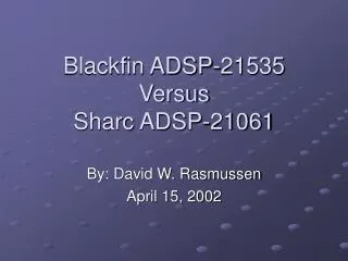
On-chip Memory Interfaces 0xFFFF 0xBFFF 0xBFFF 0x7FFF 0x3FFF 0x3FFF 0x4000 0x0000 0x0000 0x8000 0xC000 0x8000 16 Block 3 16 16 16 DM Block 2 8 16 0x9FFF 0x8000 24 Block 1 PX 24 24 Block 0 PM 24 24 0x1FFF 0x0000 2196 2195 2191
PM Bus Exchange (PX) Register PM 24 23 8 7 0 PX 15 0 7 0 16 16 DM DM • Type 32 instructionreads 24 bits from address 0x2000. Upper 16 bits are stored in AR. Lower 8 bits go to the PX register. • 24-bit indirect store • Hidden 24 bit copy • 16-bit on chip memory PX is filled by zeroes AR=PM(I4+=M5); // I4 = 0x2000 PX=AX0; // lower 8 bits PM(I4+M5)=AY0; // upper 16 bits AR=PM(I4+M5); // writes 8 lower bits to PX PM(I5+M5)=AR; // reads 8 lower from PX AR=PM(I4+=M5); // I4 = 0x8000
LDF Segment Mapping Examples ARCHITECTURE(ADSP-2191) MEMORY {seg_inttab { TYPE(PMRAM) START(0x0000) END(0x01FF) WIDTH(24) }seg_code{ TYPE(PMRAM) START(0x0200) END(0x6FFF) WIDTH(24) }seg_data2 { TYPE(PMRAM) START(0x7000) END(0x7FFF) WIDTH(24) }seg_data1 { TYPE(DMRAM) START(0x8000) END(0xFFFF) WIDTH(16) } } ARCHITECTURE(ADSP-2196) MEMORY {seg_inttab { TYPE(PMRAM) START(0x0000) END(0x01FF) WIDTH(24) }seg_code{ TYPE(PMRAM) START(0x0200) END(0x17FF) WIDTH(24) }seg_data2 { TYPE(PMRAM) START(0x1800) END(0x3FFF) WIDTH(24) }seg_data1 { TYPE(DMRAM) START(0x8000) END(0x81FF) WIDTH(16) } }
ADSP-219x On-chip Memory Count • ADSP-2191 • 32kWords of 24 bit SRAM memory • 32kWords of 16 bit SRAM memory • ADSP-2195 • 16kWords of 24 bit SRAM memory • 16kWords of 16 bit SRAM memory • 16kWords of 24 bit ROM optionally • ADSP-2196 • 8kWords of 24 bit SRAM memory • 8kWords of 16 bit SRAM memory • 16kWords of 24 bit ROM optionally 160 kByte1280 kBit 80 kByte640 kBit 40 kByte320 kBit