Download
1 / 23
230 likes | 347 Views
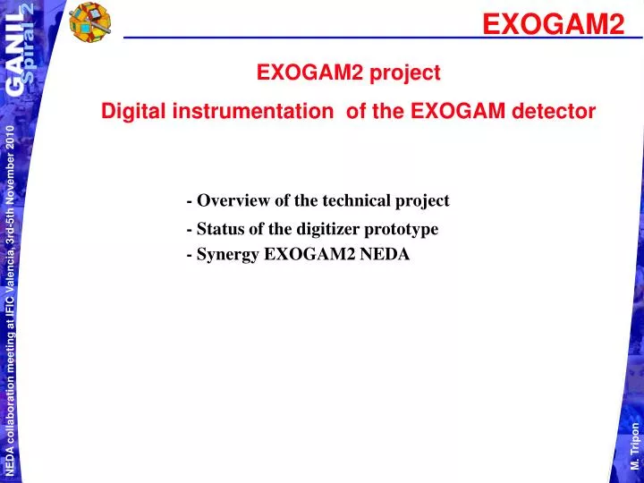
EXOGAM2. EXOGAM2 project Digital instrumentation of the EXOGAM detector. - Overview of the technical project - Status of the digitizer prototype - Synergy EXOGAM2 NEDA. 7 analog signals per crystal. 7 analog signals per crystal. Connexion. Connexion. (ICR < 100kHz per crystal).

E N D
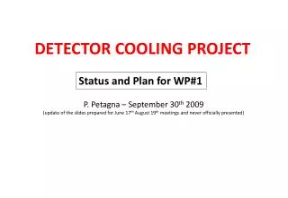
EXOGAM2 EXOGAM2 project Digital instrumentation of the EXOGAM detector - Overview of the technical project - Status of the digitizer prototype - Synergy EXOGAM2 NEDA
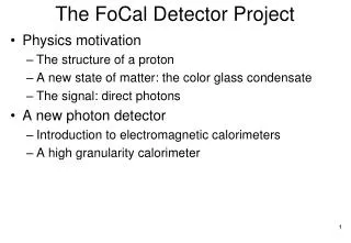
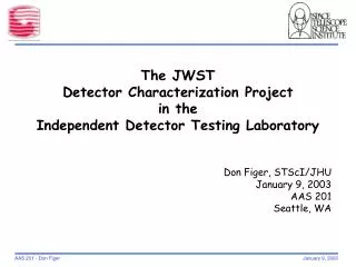
7 analog signals per crystal 7 analog signals per crystal Connexion Connexion (ICR < 100kHz per crystal) (ICR < 100kHz per crystal) box box Differential stages Differential stages Preamplifiers Preamplifiers and and 64 crystals 64 crystals 16 clovers 16 clovers test pulse generator test pulse generator One test per crystal One test per crystal => => = = 64 boxes 64 boxes 64 crystals 64 crystals 7 7 differential differential analog analog links links Control Control per NIM per NIM board board link link Global Trigger Global Trigger 1 1 optical optical link link per NIM per NIM board board Digitizing, Digitizing, and and Processing Processing Synchronization Synchronization and and 1 GTS supervisor 1 GTS supervisor Dating Dating and and N N N N N N N N N N N N N N N N N N N N N N N N N N N N 34 GTS mezzanines 1 crystal 1 crystal U U U U U U U U U U U U U U U U U U U U U U U U U U U U Per Per M M M M M M M M M M M M M M M M M M M M M M M M M M M M E E E E E E E E E E E E E E E E E E E E E E E E E E E E NIM board NIM board O O O O O O O O O O O O O O O O O O O O O O O O O O O O => => 2 2 2 2 2 2 2 2 2 2 2 2 2 2 2 2 2 2 2 2 2 2 2 2 2 2 2 2 64 NIM 64 NIM 1 1 optical optical link link per NIM per NIM board board (< 2 Gb/s) (< 2 Gb/s) boards boards KALMAN KALMAN NIM NIM 1900W 1900W processing processing 1 1 link link per NIM per NIM board board DAQ DAQ ( 6 MB/s per ( 6 MB/s per crystal crystal ) ) Ethernet Switch Ethernet Switch EXOGAM2 General architecture
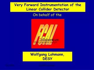
EXOGAM2 Connection box B3 FROM / TO NUMEXO2 FROM DETECTOR
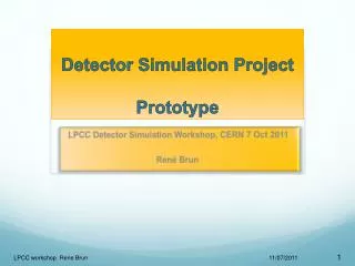
EXOGAM2 NUMEXO2 Phase 2 digitizer MGT Clocks Fast serial links Parallel links Serial Ethernet PCIe Ethernet Slow control link 100 (Adonis) Gigabit Serial link Flash PROM PPC (Linux) (VHDL) Common Logic SDRAM Virtex5FXT Optical GTS Fanin ADC Logic Interface Mux Link CLK Clocks DPRAM SRAM Delay (Local& (Physics, (Oscilloscope) Line Recovered) ADONIS) DACs Mezzanines ADC Logic (Test, control, - FADC samples collection 8*FADC Virtex6LX inspection) - Digital Processing 14 bits - Trigger 100MHz PROM - Data formatting - Inspection control (VHDL)
EXOGAM2 8 channels
EXOGAM2 16 channels
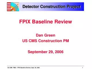
EXOGAM2 GTS implementation • 3 main functions • 200 MHz clock source • Time stamping • Trigger GTS V3 mezzanine
EXOGAM2 NUMEXO2, the NIM digitizer prototype (phase1) Block diagram
EXOGAM2 NUMEXO2, the NIM digitizer prototype (phase1) Picture of the NIM prototype
EXOGAM2 Current status (digitizer phase 1) • Firmware • Deserializer: 8 * (2 serial channels @ 700MB/s) • Moving Window Deconvolution • Discrimination • FIFO interface • Embedded software • Linux 2.6.60 • TCP/IP protocol (Ethernet) @ 400Mb/s • SPI driver and register server • Software • Characterization tools: traces, FFT, histograms, INL, DNL • Generic user interface for slow control • DAQ readout FADC serial output channel eye diagram Moving Window Deconvolution processing
EXOGAM2 To do (digitizer phase 1): • Validation of interrupt process for FIFO readout • Characterization of the digitizer with a generator • Characterization of the digitizer with a clover and a source
EXOGAM2 digitizer for NEDA instrumentation: What to notice and to do? Serial Ethernet PCIe Ethernet link 100 (Adonis) Gigabit Flash PROM PPC (Linux) (VHDL) Common Logic SDRAM Virtex5FXT Optical GTS Fanin ADC Logic Interface Mux Link CLK Clocks DPRAM SRAM Delay (Local& (Physics, (Oscilloscope) Line Recovered) ADONIS) DACs Mezzanines ADC Logic (Test, control, - FADC samples collection 8*FADC Virtex6LX inspection) - Digital Processing 14 bits - Trigger 100MHz PROM - Data formatting - Inspection control (VHDL) Custom digital processing Custom FADC mezzanine
EXOGAM2 digitizer for NEDA instrumentation: What to notice and to do ? • NEDA: • FADC mezzanines must be redesigned according to frequency bandwidth of inputs • Sample frequency of FADC? • Clock jitter? • Number of binary samples serial lines? • Power? • MDR26 connector? • SAMTEC connector?
EXOGAM2 digitizer for NEDA instrumentation: What to notice and to do? Carrier-mezzanines connecteur: QFS-026-06-75-X-D-PC4 NEDA: MDR26 Cable and connector must be tested
EXOGAM2 digitizer for NEDA instrumentation: What to notice and to do? Carrier-mezzanines connector: QFS-026-06-75-X-D-PC4 NEDA: Does pins diagram fit?
EXOGAM2 digitizer for NEDA instrumentation: What to notice and to do? FADC highlights
EXOGAM2 digitizer for NEDA instrumentation: What to notice and to do? 14 bits 12 bits
EXOGAM2 digitizer for NEDA instrumentation: What to notice and to do?
EXOGAM2 digitizer for NEDA instrumentation: What to notice and to do? Block diagram of EXOGAM2 signals processing Deserializer (2 serial lines @ 700Mb/s to 14 lines @100Mb/s) • Digital Processing • DFC • MWD • COMPUTE: • E (iner, 4 outers, BGO, CsI) • T (inner) • T30,60,90 • Mirror charges 2 Trigger Request 8*FADC Event Parameters (from mezzanines) (to Virtex 5 FXT) Setup registers Kalman interface Inspection Oscilloscope • NEDA: • - Deserializer and Digital Processing IPs must be written • - Kalman interface suppressed • - Number of Trigger Request signals > 2 • - Setup registers, Inspection and Oscilloscope IPs must be modified
EXOGAM2 digitizer for NEDA instrumentation: What to notice and to do? Is the Virtex 6 LX130T -1 powerfull enough for NEDA signals processing?
EXOGAM2 digitizer for NEDA instrumentation: What to notice and to do? Block diagram of EXOGAM2 GTS and ADC interfaces • NEDA: • DPRAM and FIFO depths? • Data format?