Download
1 / 15
170 likes | 408 Views
Globalstar II RX L-band Antenna Spherical Near Field Measurement. Damiano Trenta Thales Alenia Space Italy S.p.A. Rome, 00131 Via Saccomuro 24 Phone: (+39) 06 – 41513110 E-mail: Damiano.Trenta@thalesaleniaspace.com. Overview. Globalstar II RX L-Band Active Antenna Description

E N D
Globalstar II RX L-band Antenna Spherical Near Field Measurement Damiano Trenta Thales Alenia Space Italy S.p.A. Rome, 00131 Via Saccomuro 24 Phone: (+39) 06 – 41513110 E-mail: Damiano.Trenta@thalesaleniaspace.com
Overview Globalstar II RX L-Band Active Antenna Description TAS-Italy Spherical Near Field System General Description Test Range Validation and Comparisons Conclusions
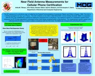
GBLII RX L-Band Active Antenna Description • The L-Band receive antenna is an active multibeam array antenna of hexagonal shape. Its assembly includes the following elements: • A Radiating Panel composed by 52 L-Band radiating elements; • 52 active chains; • A passive beam forming network (BFN) providing sixteen fixed beam laws; Total Pattern Description – Bread Board Model Polarization: LHCP; 16 total beams: 15 lateral beam and 1 central beam; Lateral Beam Squint Angle: 45 deg; Lateral Beam HPBW(max): 24 deg;
TAS-I SNFTR General Description • To satisfy the program needs, in particular to be able to guarantee an high rate production, consisting of 4 antennas per month, with low cost and high accuracy, TAS-Italy in collaboration with NSI Inc. developed a new SNF test range with the following main characteristics: • Anechoic Chamber overall dimensions: 9 x 7 x 7 m; • Absorber: 18 inches breadboard pyramidal absorber; • Positioner: Azimuth Positioner (with slip ring); • Elevation Positioner; • Roll positioner (with slip ring); • RF Subsystem: completely provided by NSI inc. High • speed, high accuracy, multi frequency and multi beam acquisition capabilities; • Antenna Patterns Acq. Needed Time: 20 min;
TAS-I SNFTR General Description AUT Box Main Components 1:16 RF Switch f axis 3 [m] • AUT 1:16 Multiplexing Switch AUT DC Power Control Unit OEWG WR 510 • AUT Mechanical Ground System Equipment:design tooptimize: • The mechanical fixation – AUT alignment; • the RF and DC cables mate and de-mate operations; • The scattering and polarization purity • performances Probe Tower q axis 3 [m] • AUT DC Power Control Unit • it was designed to guarantee the proper DC power supply to the AUTin terms of ripples and signal variations and /or discontinuity due to the azimuth and the roll stage movements.
Test Range Validation and Comparisons Main Steps • Measurement of a SGH WR650 • Comparison between TAS-F and TAS-I Measurements. The comparisons between the measurements of three facilities were done. The antenna, was tested in Toulouse, in a quasi far-field test range, in TAS-I in a Spherical Near Field Test range (already available and validated) and the new one. Comparisons in terms of max Directivity, Crosspolar peak, Copolar and Crosspolar patterns were done. • Error budget Definition. Using the 18 Terms Error budget Technique an analysis of the measurement uncertainties has been done.
Comparison between TAS-F and TAS-I Measurements TAS-F (Red Line) vs TAS-I (Black - Already Aveable) TAS-F (Red Line) vs TAS-I (Black – New One)
Comparison between TAS-F and TAS-I Measurements TAS-F (Red Line) vs TAS-I (Black - Already Aveable) TAS-F (Red Line) vs TAS-I (Black – New One)
Comparison between TAS-F and TAS-I Measurements TAS-F (Red Line) vs TAS-I (Black - Already Aveable) TAS-F (Red Line) vs TAS-I (Black – New One)
Comparison between TAS-F and TAS-I Measurements TAS-F (Red Line) vs TAS-I (Black - Already Aveable) TAS-F (Red Line) vs TAS-I (Black – New One)
Comparison between TAS-F and TAS-I Measurements TAS-F (Red Line) vs TAS-I (Black - Already Aveable) TAS-F (Red Line) vs TAS-I (Black – New One)
Comparison between TAS-F and TAS-I Measurements TAS-F (Red Line) vs TAS-I (Black - Already Aveable) TAS-F (Red Line) vs TAS-I (Black – New One)
Error Budget Definition Using the 18 Terms Error budget Technique an analysis of the measurement uncertainties has been done. Main Beam Region (MBR): Spatial region of each beam where the level is higher than -10dB; Side Lobe Region(SLR) & Cross Region: Circle with 54.3 deg radius; The worst case error level is evaluated, taking into account the 99% (3 sigma) of the total number of points inside each region. Room Scattering Error Pattern
Conclusions A general description of the New Spherical Near Field installed and validated in TAS-I Rome to support the GLB2 L-band RX Active antenna, is given The comparisons of the Active Antenna BreadBoard measurements, in terms of copolar and cross polar patterns, and post-processing data, show a very good convergence - all the evaluated delta fall in the range of the total uncertainty of the relevant facilities . This ensured a successful test facility validation and the definition of performance uncertainty budgets for the GBL2 antenna production program