Download
1 / 23
230 likes | 398 Views
HOME CONTROL SYSTEM. By: Justin E. Klumpp & Leo L.S. Wan. Base Microcontroller. Motorola 9S12DP256B Bus Frequency at 24MHz Memory 256k bytes Flash 12k bytes RAM 4k bytes EEPROM. Kernel Choice. MicroC/OS-II Real-Time preemptive multitasking kernel

E N D
HOME CONTROL SYSTEM By: Justin E. Klumpp & Leo L.S. Wan
Base Microcontroller • Motorola 9S12DP256B • Bus Frequency at 24MHz • Memory • 256k bytes Flash • 12k bytes RAM • 4k bytes EEPROM
Kernel Choice • MicroC/OS-II • Real-Time preemptive multitasking kernel • Semaphores used to communicate between tasks • Tick period, 1ms
Kernel Tasks & Priority • StartTask Priority:4 • ControlTask Priority:5 • RTCTask Priority:6 • DAATask Priority:7 • SCITask Priority:8 • KeyTask Priority:9
StartTask • Description: Initializes MicroC/OS and creates the other tasks during startup • Priority: 4 • Period: Executes once at startup • Execution Time: 150ms estimated
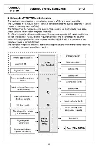
ControlTask • Description: This task controls all remote modules and intertask communication. It interprets all user’s command, phone line termination, sprinkler control, DTMF input, and User Interface control. • Priority: 5 • Execution Time: 4ms (max) • Period: 10 ms (Periodic) • CPU Load: 0.4
RTCTask • Description: Receive real time data from the DS1305 real time clock. • Priority: 6 • Execution Time: 35 us • Period: 1 second (Periodic) • CPU Load: 0.000035
DAATask • Description: This task will scan the RING pin on the DAA chip for valid ring signals • Priority: 7 • Execution time: 50us • Period: 20ms • CPU Load: .0025
SCITask • Description: Poll the SCI Receive Data Register Full (RDRF) flag, once flag is set, SCI clocks in data into a buffer. • Priority: 8 • Execution Time: 50us. • Period: 10 ms (Periodic) • CPU Load: 0.005
KeyTask • Description: The main keypad scanning task. It scans the keypad and updates the keypad buffer if a key press was verified. • Priority: 9 • Period: 10ms • Execution Time: 50us • CPU Load: 0.005 Code Composed by: Todd Morton
Total CPU Load • Max CPU Load: 0.4 + 0.000035 + 0.0025 + 0.005 + 0.005 = 0.412535 • Average CPU Load: 0.25
LCD Flow Diagram UI.c Public Function(s) LCD Driver LCD I/O LcdInit() LcdDispStrg() TimeSet() LcdDispChar() Lcd() PhoneSet() LcdMoveCursor() LcdCursor() AlarmSet() LcdDispTime() UIMenu() LcdClrDisp()
Keypad Flow Diagram Keypad I/O Public Function(s) Keypad Driver 10msec KeyTask() KeyInit() Key.buffer KeyPend() KeyCode Table Key.flag
Control Task Flow Diagram Awaiting Flags Functions to Call Control Task TimeSet() KeyPend() PhoneSet() AlarmSet() 10msec TimePend() UIMenu() ControlTask() SCIPend() PlayMSG() DTMFWrite() RingPend() EESectModify() DTMFRead() WriteSCI() LcdDispTime()
MCU: Control Modules • MCU: PSoC CY8C29466 • Operating Voltage: 5 volts • Clock Frequency: 6 MHz • Microcontroller will only run one continuous task so no kernel is required • Memory, MCU #1 (Bytes): 25 RAM, 1042 ROM • Memory, MCU #2 (Bytes): 20 RAM, 904 ROM
AlarmTask • Description: Send a byte of data at a rate of 300bps. The byte of data contains the current state of the alarm sensor, and a unique alarm ID number. • Period: Runs on a sleep timer that wakes up every second • Execution time: ~1us • CPU Load: 0.000001
ISR: Sleep Timer • Description: This timer is used to put the Microcontroller into a sleep mode, where the current consumption on the PSoC is ~2.9uA. • Execution Time: ~1us • Period: 1 second • CPU Load: 0.000001
Data Flow Diagram: ISR Sleep Timer Interrupt
LightCtrlTask • Description: Polls on a valid data flag to be set, if set clocks in bits of data. Receive byte of data at 300bps; data contains control bits to turn on/off output pins. Controls the state of a relay; on or off. • Execution time: ~1us • Period: Continuous Operation • CPU Load: 1