Download
1 / 36
360 likes | 482 Views
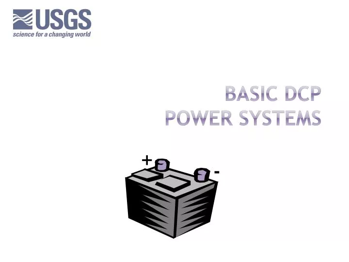
Basic DCP Power Systems. +. -. Power Connectors. This is the standard USGS connection for the DCP. Some manufacturers do not recommend using a methode connector. However, we find this useful and adequate so long as the system is well maintained. DCP. Methode Connector. `. Parallel

E N D
Power Connectors • This is the standard USGS connection for the DCP. • Some manufacturers do not recommend using a methode connector. However, we find this useful and adequate so long as the system is well maintained. DCP Methode Connector
` Parallel Harness Wiring • The DCP should be connected directly to the battery • Not to the regulator • Not through a parallel harness . + - DCP X
Current Draw • This is a representation of the same circuit with the charging system removed. • This circuit contains a theoretical battery. It’s voltage does not change unless specified. + - DCP Battery 12.70 Volts
CURRENT DRAW • Under normal conditions, when power is applied, a DCP completes it’s boot-up routine then goes into a low power mode called the quiescent state (sleep mode). • By inserting an ampere meter in the circuit, we can determine that the quiescent current for this DCP is 10mA. Current may be higher or lower for other types of DCPs. 00.01 + - DCP Quiescent = 0.01 Ampere (A) 10 milliampere (mA) Battery 12.70 Volts
CURRENT DRAW • When it is time for the DCP to take a measurement or perform another activity, it will awaken. • This DCP draws 0.25A (250mA). 00.25 + - DCP Awake = 0.25 Ampere (A) 250 milliampere (mA) Battery 12.70 Volts
CURRENT DRAW • Under normal conditions, when power is applied, a DCP completes it’s boot-up routine then goes into a low power mode called the quiescent state (sleep mode). • By inserting an ampere meter in the circuit, we can determine that the quiescent current for thisDCP is 10ma. Current may be higher or lower for other types of DCPs. 03.50 + - DCP Transmitting = 3.50 Ampere (A) 3500 milliampere (mA) Battery 12.70 Volts
CIRCUIT Resistance • Ideally, the DCP should be the total resistance (load) in the circuit and thus Rt • However here Rturepresents the total unwanted circuit resistance + - DCP Rt Rtu = 0 ohms Battery 12.70 Volts
CIRCUIT Resistance • If the system is not properly maintained, corrosion might form on a battery terminal. This causes resistance in the circuit wiring.
CIRCUIT Resistance • If the system is not properly maintained, corrosion might form on a battery terminal. This causes resistance in the circuit wiring. • One-half ohm is a very small amount of resistance. Some fuses have this much resistance. • If this is the only unwanted resistance in the circuit, then Ra is the total circuit resistance Rtu. + - DCP Ra = 0.5 Ohms Rtu = Ra = 0.5 ohms Battery 12.70 Volts
CIRCUIT Resistance • In this example, the methode connector used for the battery wiring was actually meant to be used with a smaller gauge wire. • During installation, a few strands of wire were severed which caused a less conductive path.
CIRCUIT Resistance • In this example, the methode connector used for the battery wiring was actually meant to be used with a smaller gauge wire. • During installation, a few strands of wire were severed which caused a less conductive path. • Rb contributes and thus adds to Rtu. + - DCP Rb = 0.1 Ohms Ra = 0.5 Ohms Rtu = Ra+Rb = 0.6 ohms Battery 12.70 Volts
CIRCUIT Resistance • While stripping the wire to connect to the DCP, a few strands of wire were cut. • More resistance!
CIRCUIT Resistance • While stripping the wire to connect to the DCP, a few strands of wire were cut. • More resistance! + - Rc = 0.2 Ohms DCP Rb = 0.1 Ohms Ra = 0.5 Ohms Rtu = Ra+Rb+Rc = 0.8 ohms Battery 12.70 Volts
CIRCUIT Resistance • This wire happen to run right where the tool box and other objects were placed during site visits. • The insulation was ripped, then liquid was spilled in the area causing the wire to corrode adding even more resistance.
CIRCUIT Resistance • This wire happen to run right where the tool box and other objects were placed during site visits. • The insulation was ripped, then liquid was spilled in the area causing the wire to corrode adding even more resistance. + - Rd = 0.3 Ohms Rc = 0.2 Ohms DCP Rb = 0.1 Ohms Ra = 0.5 Ohms Rtu = Ra+Rb+Rc+Rd = 1.1 ohms Battery 12.70 Volts
CIRCUIT Resistance • The total resistance Rtu is very small. • However it indicates deterioration of the circuit is present. + - Rb Rd Rc DCP Ra Rtu = 1.1 ohms Battery 12.70 Volts
Ohms Law • Ohm's law applies to electrical circuits • It states that the current through a conductor between two points is directly proportional to the potential difference (i.e. voltage drop or voltage) across the two points, and inversely proportional to the resistance between them. • The mathematical equation that describes this relationship is: V = I * R • Where: • V = Voltage • I = Current • R = Resistance
CIRCUIT Resistance • In an active circuit, since V=IR, a small amount of the applied voltage will be dropped across each resistance. • We can measure this voltage or calculate it. In this case we will calculate it. 0.005 + - Rb Rd Rc DCP Ra Quiescent = 0.01 A (10 mA) Va = I Ra = 0.01 A x 0.5 ohms = 0.005 V Battery 12.70 Volts
CIRCUIT Resistance • In an active circuit, since V=IR, a small amount of the applied voltage will be dropped across each resistance. • We can measure this voltage or calculate it. In this case we will calculate it. 0.001 + - Rb Rd Rc DCP Ra Quiescent = 0.01 A (10 mA) Vb = I Rb = 0.01 A x 0.1 ohms = 0.001 V Battery 12.70 Volts
CIRCUIT Resistance • In an active circuit, since V=IR, a small amount of the applied voltage will be dropped across each resistance. • We can measure this voltage or calculate it. In this case we will calculate it. 0.002 + - Rb Rd Rc DCP Ra Quiescent = 0.01 A (10 mA) Vc = I Rc = 0.01 A X 0.2 ohms = 0.002 V Battery 12.70 Volts
CIRCUIT Resistance • In an active circuit, since V=IR, a small amount of the applied voltage will be dropped across each resistance. • We can measure this voltage or calculate it. In this case we will calculate it. 0.003 + - Rb Rd Rc DCP Ra Quiescent = 0.01 A (10 mA) Vd = I Rd = 0.01 X 0.3 = 0.003 V Battery 12.70 Volts
CIRCUIT Resistance • The total voltage dropped across these resistances will reduce the battery voltage supplied to the DCP 12.689 + - Rb Rd Rc Ra DCP 12.689 V Quiescent = 0.01 A (10 mA) VTD = Va+Vb+Vc+Vd VTD = .005 + .001 + .002 + .003 = .011 VDCP = VBAT – VTD VDCP = 12.70 - .011 = 12.689 Battery 12.70 Volts
CIRCUIT Resistance • We can also find this voltage drop by multiplying the current by the total resistance, or we can measure the voltage at the DCP. Let’s follow this through a measurement and transmission. 12.689 + - Rb Rd Rc Ra DCP 12.689 V Quiescent = 0.01 A (10 mA) Rtu = 1.1 ohms VTD = I x Rtu = .011 VDCP = VBAT - (I x Rtu) VDCP = 12.70 - (.011) = 12.689 Battery 12.70 Volts
CIRCUIT Resistance • When it’s time to make a measurement, the DCP awakes. This is probably more current than most data loggers with sensors draw. The circuit would probably have no problem powering a logger, and data would be logged. 12.425 + - Rb Rd Rc Ra DCP 12.425 V Awake = 0.25 A (250 mA) RTU = 1.1 ohms VTD = I x Rtu = .275 VDCP = VBAT - ( .275) VDCP = 12.70 - .275 = 12.425 Battery 12.70 Volts
CIRCUIT Resistance • The voltage is too low although the battery is still good. • This demonstrates that small wiring defects may not cause problems until circuit current increases significantly. 8.850 + - Rb Rd Rc Ra DCP 8.850 V Transmitting = 3.50 A (3500 mA) RTU = 1.1 ohms VTD = I x Rtu = 3.5 * 1.1 = 3.850 VDCP = VBAT - ( 3.850 ) VDCP = 12.70 – 3.850 = 8.850 Battery 12.70 Volts
RISK OF WIRING Fault • Risk can be evaluated by dividing the actual number of connection points by the minimum possible connection points. 10 / 4 = 2.5 x 100 = 250%increased risk of fault + - 7 5 9 3 4 10 6 DCP 8 1 2 Battery 12.70 Volts
RISK OF WIRING Fault • Even with good wiring, each connection increases the chance of wiring faults. • Some manufacturers advise against additional connecters between the DCP and battery. • Their argument is that each connector significantly increases the risk of a wiring fault. + - 7 5 9 3 4 10 6 DCP 8 1 2 Battery 12.70 Volts
RISK OF WIRING Fault • 18 / 4 = 4.5 * 100 = 450% increased risk of fault 9 8 + - 18 10 7 13 17 11 6 3 14 16 5 4 12 15 DCP 1 2 Battery 12.70 Volts
RISK OF WIRING Fault • This previous diagram includes a parallel cable harness which dramatically increases the risk of a wiring fault. • Long ago, these were used to keep from losing the cxonfiguration and data during battery exchange. Now that DCPs have static memory, it is best to disconnect and reconnect. • Nonetheless, download the configuration and data before any power change. • As a best practice, do this upon arrival at the site, before performing any servicing.
CIRCUIT Resistance • Even in a system with good wiring, the voltage will drop slightly because of internal battery and circuit wire resistance. • All batteries and wire have some resistance. • A battery with excessive internal resistance is called a soft battery. 12.39 12.40 + - DCP 12.39 V Battery 12.70 Volts Transmitting = 3.50 A (3500 mA)
CIRCUIT Resistance • A battery with too much internal resistance causes the same problems as bad wiring. • A battery which is not being charged will have a higher internal resistance as the capacity becomes lower. Also, if one has been overcharged it will vent and dry out, or if one has been discharged too deeply it will deteriorate. All will develop internal resistance. • This is not uncommon. 8.85 8.85 + - DCP 12.39 V 1.1 ohms Battery 12.70 Volts Transmitting = 3.50 A (3500 mA) VDCP = VBAT – VTD = 12.7 - (1.1 x 3.5) = 8.85V
SOFT Batteries • Another problem that can occur in a system with a soft battery, is that the charging circuit provides enough current to operate the DCP measurement mode, but will not provide enough current to transmit. • The battery problem is masked until the current draw exceeds the charge current. • Always remove the charger prior to testing the battery. • It’s best to program the DCP to measure voltage during or immediately after a transmission. 13.85 13.85 + - DCP
SOFT Batteries • Even a meter will load the battery slightly, however, it essentially insignificant. • If we measured the soft battery with a typical multi-meter, we would read the full voltage since the meter’s resistance is very high compared to the battery’s internal resistance. • Without the battery loaded we really can’t determine much. • Notice the calculation. With just two digits past the decimal displayed, the meter would round this to 12.70 Volts. 12.70 + - RBAT = 1000 ohms RMETER = 10,000,000 ohms ITOTAL = V/R = 12.7 / 10,001,000 = 1.27mA VBAT-DROP = .00127 V VMETER = 12.7 - .00127 = 12.6987 or 12.70 V Battery 12.70 Volts 1000 ohms
SOFT Batteries • With the charger removed from a soft battery, the DCP would not awaken. • The load would cause the battery to produce very little voltage. • As previously shown, without the load, this same battery measured 12.70V 12.70 2.70 + - DCP Asleep = .01 A VDCP = 12.7 - (.01 x 1000) = 2.7V 1000 ohms Battery 12.70 Volts
SITE VISITS • This presentation should assist you in understanding power problems that may cause transmission loss. • As a best practice, the first thing you should do before any inspection or testing, is to download any data that may be stored in the DCP. • To eliminate problems: On each visit to a site; • Download data first • Inspect the site wiring and connections to ensure they are in good shape. • Check the charge circuit. • Test the battery loaded to the max current the circuit will draw. Be sure to disconnect the charge circuit when testing the battery.