Download
1 / 25
520 likes | 1.22k Views
An Active EMI reduction IC WT6001. POWERELAB LIMITED. A Power Converter Technology Provider. All products must comply with various EMI regulations EMI reduction in switching power supply is mainly carried out by passive filters filter chokes are big and dissipative

E N D
An Active EMI reduction ICWT6001 POWERELAB LIMITED A Power Converter Technology Provider
All products must comply with various EMI regulations EMI reduction in switching power supply is mainly carried out by passive filters filter chokes are big and dissipative Y capacitors introduce leakage current It is desired to cut down filter requirement EMI in switching power supplies
EMI reduction by active method It cuts down common mode current in SMPS A small SO8 IC that cuts down common mode choke size reduces Y capacitor requirement eliminates thermal problem in common mode chokes increase SMPS overall efficiency reduces product cost An active EMI IC is introduced
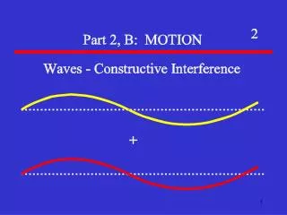
Common mode current is a major contributor of conducted EMI It is difficult to trace as its path is not readily seen on a circuit diagram Common mode current in SMPS Power eLab
Generation of common mode current in SMPS & the IC Load LISN spectrum
The added Y-cap can effectively reduce the common mode current due to the parasitic capacitance of the load to the earth The maximum allowed value is limited by the leakage current requirement Safety requirement and EMI limits
Equivalent to a Y-cap with very large value within the EMI concerned frequency range only Capacitance remains low in the leakage current test frequency range (50 – 800Hz) Provide effective EMI solution Greatly reduce the common mode filter requirement Reduce converter size and improve conversion efficiency Built-in electrical voltage surge protection which can easily pass EN61000-4-4 and EN61000-4-5 immunity standard Independent of converter power level, it can handle high power converters The IC provides an effective Y-cap booster
An application example – 120W power adaptor • The original EMI filter design cannot pass the EN55022 class B limit • Filter component: 2 x 20mm high mu toroid 2 x 0.15uF X – cap 1 x 1n Y1-cap
Original filter circuit • It is a commonly used filter configuration • L2B is wound with many turns which intends to suppress the low to mid-frequency common mode noise. Its leakage inductance together with C1 also provides differential mode noise filtering • L1B is a single layer, bi-filer wound common mode choke for high frequency common mode noise filtering
EMI measured results – Original design high line low line • At 230Vac input, detailed measurement showed that the circled regions can only marginally pass or fail to meet the average limit line. • The lower frequency region seems to be caused by differential mode noise • The high frequency region is caused by common mode noise
EMI solution – A better one using Y-cap booster • Y-cap booster is used to replace the 1n Y-cap • In addition to the removal of L2B, L1B can be further reduced to a 9mm toroid with only a few turns
Filter size reduction Failed design even with more cost, loss and bigger size for the filter Passed design using Y-cap booster with much smaller filter size that saves cost, power and space
Filter comparison Y-cap booster demo board
Y-cap booster allow small Y-caps and meets leakage current requirement Greatly reduce product design period and resources It can be applied to any position with conventional Y-cap Significantly reduces the size and loss of common mode choke implies higher power density and efficiency EMI less sensitive to transformer winding capacitance implies more rooms for improving transformer coupling Very suitable for equipment required lower leakage current Summary
8 pin SO IC The IC WT6001
A very useful way to observe the effectiveness of cancellation is by probing the waveform across the primary & secondary Observation of cancellation by an oscilloscope Floating oscilloscope
Waveforms observed before & after application of the EMI IC Observation of cancellation by an oscilloscope A 1 nF Y-cap across primary & secondary EMI IC circuit across primary & secondary
Class II – no ground connection, Y-cap only Waveform shows cancellation effect Waveform across primary & secondary High noise level
Class II – no ground connection, EMI IC applied Waveform shows cancellation effect Upper Ch : Waveform across primary & secondary Lower Ch : IC output Low noise level
Class I –ground connection, Y-cap only Waveform shows cancellation effect Upper Ch : Waveform across primary & secondary High noise level
Class I – ground connection, EMI IC applied Waveform shows cancellation effect Upper Ch : Waveform across primary & secondary Lower Ch : IC output Low noise level
Procedures to implement the IC to a switching power supply • Make sure that there is enough differential mode choke. • Differentiate between Class I & Class II products to see whether the IC can apply • Class I product – Put a big capacitor between the primary & secondary • Class II product – Short circuit the primary & secondary • If there is significant reduction in common mode noise on the spectrum, apply the Class I or Class II circuit accordingly. • Put in small common mode choke for high frequency noise suppression. The IC works up to 7 MHz.
To cater for different power supply environment, the following components can be trimmed Y-cap connected to the IC output (pin 5) Feedforward resistors in the circuit for class I products Refer to datasheet for details Trimming process
The IC works best when Vcc is close to 15V The power supply should be properly laid out for best effect Points to note


![What is an IC ? [integrated circuit]](https://cdn1.slideserve.com/2972450/slide1-dt.jpg)